


Homework Answers

![a O = 250], 20-50°3 9 = 20 - 2Qp = 50° 21.80° = 28.2003 ones Tave – Roos g => 15-(80.78x Los 28-20) Exty = – Rsim --R sin q](http://img.homeworklib.com/questions/6218d040-0815-11eb-8555-239bd0e8e793.png?x-oss-process=image/resize,w_560)

 In case of any query please comment . If you have liked the
solution then
please THUMBS UP.
In case of any query please comment . If you have liked the
solution then
please THUMBS UP.
Add Answer to:
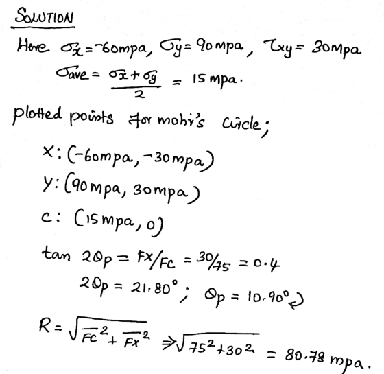
Solve using Mohr's Circle
90 MPa 30 MPa 60 MPa Fig. P7.14 7.13 through 7.16 For...
Required information Solve the following problems using Mohr's circle Given: P 84 MPa P 50 MPa...
 Required information Solve the following problems using Mohr's circle Given: P 84 MPa P 50 MPa Draw Mohr's circle and use it to determine the normal and shearing stresses after the element shown has been rotated through 25 clockwise. (Round the final answers to two decimal places.) Normal stresses: MPa (+ tensile; - compressive) Ox' Gy[ MPa (+tensile; - compressive) Shearing stress: Txy MPa (+CCW on the positive X-face)
14.25 Solve Probs. 14.5 and 14.9, using Mohr's circle. 14.5 through 14.8 For the given state...
 14.25 Solve Probs. 14.5 and 14.9, using Mohr's circle. 14.5 through 14.8 For the given state of stress, determine (a) the pri planes, (b) the principal stresses. 14.9 through 14.12 For the given state of stress, determine (a) the orienta- tion of the planes of maximum in-plane shearing stress, (b) the maxi- mum in-plane shearing stress, (c) the corresponding normal stress. 40 MPa 35 MPa 60 MPa Fig. P14.5 and P14.9
Required information Solve the following problems using Mohr's circle. Given: P= 12.5 ksi S ksi 6...
 Required information Solve the following problems using Mohr's circle. Given: P= 12.5 ksi S ksi 6 ksi Draw Mohr's circle and use it to determine the normal and shearing stresses after the element shown has been rotated through 25° clockwise. (Round the final answers to two decimal places.) Normal stresses: Ox'= yksi (+ tension; - compression) Oy= ksi (+ tension; - compression) Shearing stress: Tx'y'= C k si (+ CCW on the positive X-face)
Use Mohr's circle 5. For the stress element shown, use components associated with an element rotated...
 Use Mohr's circle
5. For the stress element shown, use components associated with an element rotated counterclockwise 30°. Show values on the rotated element. alytical means or Mohr's circle to determine the stress Use previous "diameter" determined by "plotting" the given stresses, then ADD 60° CCW from that diameter to find new points on the circumference of Mohr's circle. 60 MPa 30° 100 MPa Once again, try just using plain geometry to determine those points. 48 MPa
Use Mohr's circle
5. For the stress element shown, use components associated with an element rotated counterclockwise 30°. Show values on the rotated element. alytical means or Mohr's circle to determine the stress Use previous "diameter" determined by "plotting" the given stresses, then ADD 60° CCW from that diameter to find new points on the circumference of Mohr's circle. 60 MPa 30° 100 MPa Once again, try just using plain geometry to determine those points. 48 MPa
THE FOLLOWING PROBLEMS ARE TO BE SOLVED WITH A COMPUTER. Problem 1 A state of plane...
 THE FOLLOWING PROBLEMS ARE TO BE SOLVED WITH A COMPUTER. Problem 1 A state of plane stress is defined by the stress components 0, 0, and I associated with the element shown in Figure (a). i. Write a computer program that can be used to calculate the stress components 6, 5, and try" associated with the element after it has rotated through an angle about the z axis as shown in Figure (b). 1 F: Use this program to solve...
Consider the given state of stress. Take X = 10 MPa and Y = 45 MPa....
 Consider the given state of stress. Take X = 10 MPa and
Y = 45 MPa.
Determine the principal planes using Mohr's circle. a) The
principal planes are at − ° and °.
Determine the principal stresses using Mohr's circle. b)The
minimum principal stress is − MPa, and the maximum
principal stress is MPa.
Determine the orientation of the planes of maximum in-plane
shearing stress using Mohr's circle. c) The orientation of the
plane of maximum in-plane shearing stress in the first quadrant
is °....
Consider the given state of stress. Take X = 10 MPa and
Y = 45 MPa.
Determine the principal planes using Mohr's circle. a) The
principal planes are at − ° and °.
Determine the principal stresses using Mohr's circle. b)The
minimum principal stress is − MPa, and the maximum
principal stress is MPa.
Determine the orientation of the planes of maximum in-plane
shearing stress using Mohr's circle. c) The orientation of the
plane of maximum in-plane shearing stress in the first quadrant
is °....
Problem 1.8. Mohr's circle Draw Mohr's circle for the state of stress defined by 01 =...
 Problem 1.8. Mohr's circle Draw Mohr's circle for the state of stress defined by 01 = 80 MPa, 02 = -20 MPa and T12 = 40 MPa. Using this circle, (1) calculate the stress on axes rotated 60 degrees counterclock- wise from the reference axes, and (2) determine the principal stresses and the corresponding directions. Do these results agree with the results in section 1.3.3?
3. The state of plane stress at a point is shown on the element below. Construct...
 3. The state of plane stress at a point is shown on the element below. Construct Mohr's circle. Determine the principal stresses acting at this point and their orientation D,. Also determine the maximum in-plane shear stresses and the orientation of the element upon which they act. What is the state of stress if it is rotated 20° counterclockwise? (20 points) 90 MPa 60 MPa -20 MPa
Mohr's Circle: For the state of stress shown below, sketch the plane stress Mohr Circle on...
 Mohr's Circle: For the state of stress shown below, sketch the plane stress Mohr Circle on a graphing paper (to scale and using drawing instruments). Staple it to this coversheet. 10 ksi 20 ksi In the space below sketch the element showing the principal planes and the principal stresses (remember to show the angle the element makes with either the X or the Y axis) In the space below sketch the element showing the maximum in-plane shearing stresses, associated normal...
There is one force element in xy-axes, with Sigma (x) = 30 MPa, Sigma (y) =...
 There is one force element in xy-axes, with Sigma (x) = 30 MPa, Sigma (y) = 60 MPa, and Tao (xy) = 40 MPa. (Sigma for normal stress and Tao for shear stress) (1) Draw a force element with all above stresses labeled in xy-axes and translate the information on a Mohr's circle; (2) Rotate the force element 30 degree (counterclockwise). Use Mohr's circle to derive the stresses in this new element; (3) Use Mohr's circle to determine the principal...
 Required information Solve the following problems using Mohr's circle Given: P 84 MPa P 50 MPa Draw Mohr's circle and use it to determine the normal and shearing stresses after the element shown has been rotated through 25 clockwise. (Round the final answers to two decimal places.) Normal stresses: MPa (+ tensile; - compressive) Ox' Gy[ MPa (+tensile; - compressive) Shearing stress: Txy MPa (+CCW on the positive X-face)
 14.25 Solve Probs. 14.5 and 14.9, using Mohr's circle. 14.5 through 14.8 For the given state of stress, determine (a) the pri planes, (b) the principal stresses. 14.9 through 14.12 For the given state of stress, determine (a) the orienta- tion of the planes of maximum in-plane shearing stress, (b) the maxi- mum in-plane shearing stress, (c) the corresponding normal stress. 40 MPa 35 MPa 60 MPa Fig. P14.5 and P14.9
 Required information Solve the following problems using Mohr's circle. Given: P= 12.5 ksi S ksi 6 ksi Draw Mohr's circle and use it to determine the normal and shearing stresses after the element shown has been rotated through 25° clockwise. (Round the final answers to two decimal places.) Normal stresses: Ox'= yksi (+ tension; - compression) Oy= ksi (+ tension; - compression) Shearing stress: Tx'y'= C k si (+ CCW on the positive X-face)
 Use Mohr's circle
5. For the stress element shown, use components associated with an element rotated counterclockwise 30°. Show values on the rotated element. alytical means or Mohr's circle to determine the stress Use previous "diameter" determined by "plotting" the given stresses, then ADD 60° CCW from that diameter to find new points on the circumference of Mohr's circle. 60 MPa 30° 100 MPa Once again, try just using plain geometry to determine those points. 48 MPa
Use Mohr's circle
5. For the stress element shown, use components associated with an element rotated counterclockwise 30°. Show values on the rotated element. alytical means or Mohr's circle to determine the stress Use previous "diameter" determined by "plotting" the given stresses, then ADD 60° CCW from that diameter to find new points on the circumference of Mohr's circle. 60 MPa 30° 100 MPa Once again, try just using plain geometry to determine those points. 48 MPa
 THE FOLLOWING PROBLEMS ARE TO BE SOLVED WITH A COMPUTER. Problem 1 A state of plane stress is defined by the stress components 0, 0, and I associated with the element shown in Figure (a). i. Write a computer program that can be used to calculate the stress components 6, 5, and try" associated with the element after it has rotated through an angle about the z axis as shown in Figure (b). 1 F: Use this program to solve...
 Consider the given state of stress. Take X = 10 MPa and
Y = 45 MPa.
Determine the principal planes using Mohr's circle. a) The
principal planes are at − ° and °.
Determine the principal stresses using Mohr's circle. b)The
minimum principal stress is − MPa, and the maximum
principal stress is MPa.
Determine the orientation of the planes of maximum in-plane
shearing stress using Mohr's circle. c) The orientation of the
plane of maximum in-plane shearing stress in the first quadrant
is °....
Consider the given state of stress. Take X = 10 MPa and
Y = 45 MPa.
Determine the principal planes using Mohr's circle. a) The
principal planes are at − ° and °.
Determine the principal stresses using Mohr's circle. b)The
minimum principal stress is − MPa, and the maximum
principal stress is MPa.
Determine the orientation of the planes of maximum in-plane
shearing stress using Mohr's circle. c) The orientation of the
plane of maximum in-plane shearing stress in the first quadrant
is °....
 Problem 1.8. Mohr's circle Draw Mohr's circle for the state of stress defined by 01 = 80 MPa, 02 = -20 MPa and T12 = 40 MPa. Using this circle, (1) calculate the stress on axes rotated 60 degrees counterclock- wise from the reference axes, and (2) determine the principal stresses and the corresponding directions. Do these results agree with the results in section 1.3.3?
 3. The state of plane stress at a point is shown on the element below. Construct Mohr's circle. Determine the principal stresses acting at this point and their orientation D,. Also determine the maximum in-plane shear stresses and the orientation of the element upon which they act. What is the state of stress if it is rotated 20° counterclockwise? (20 points) 90 MPa 60 MPa -20 MPa
 Mohr's Circle: For the state of stress shown below, sketch the plane stress Mohr Circle on a graphing paper (to scale and using drawing instruments). Staple it to this coversheet. 10 ksi 20 ksi In the space below sketch the element showing the principal planes and the principal stresses (remember to show the angle the element makes with either the X or the Y axis) In the space below sketch the element showing the maximum in-plane shearing stresses, associated normal...
 There is one force element in xy-axes, with Sigma (x) = 30 MPa, Sigma (y) = 60 MPa, and Tao (xy) = 40 MPa. (Sigma for normal stress and Tao for shear stress) (1) Draw a force element with all above stresses labeled in xy-axes and translate the information on a Mohr's circle; (2) Rotate the force element 30 degree (counterclockwise). Use Mohr's circle to derive the stresses in this new element; (3) Use Mohr's circle to determine the principal...
Most questions answered within 3 hours.
-
Where is the error in this code sequence?
String s1 = "Hello";
String s2 = "ello";...
asked 10 months ago -
Financial data for Joel de Paris, Inc., for last year
follow:
Joel de Paris, Inc.
Balance...
asked 10 months ago -
Consider this reaction:
Al2(SO4)3 (aq)+ BaCl3
(aq) Al2Cl6 (aq)- +
3BaSO4(s) . What is the...
asked 10 months ago -
Suppose that Savneet is considering increasing her
recent random sample from 20 car rentals to 40...
asked 10 months ago -
Trucks arrive at an unloading terminal at an average rate of 120
per hour.
Trucks arrive...
asked 10 months ago -
Why are methanol and ethanol completely soluble in water while
octanol is not very little soluble....
asked 10 months ago -
A facilities manager at a university reads in a research report
that the mean amount of...
asked 10 months ago -
When the CuSO4 is rehydrated by adding water to the anhydrous
compound, is this an endothermic...
asked 10 months ago -
A ray of sunlight is passing from diamond into crown glass; the
angle of incidence is...
asked 10 months ago -
A block of mass 0.249 kg is placed on top of a light, vertical
spring of...
asked 10 months ago -
how do the kidneys compensate in the presences of acidosis
a) trigger hyperventilate
b) reserve acid...
asked 10 months ago -
Question 501 pts
The rental rate of capital to the firm increases. Which of the
following...
asked 10 months ago