For the planar mechanism of figure below, link 4 servers as slider support which is free to rotate about the z axis, but has point D kept stationary. Link 3 is a rigid member continuous over the rotational joint B. The lengths of the links 2 and 5 are respectively 3 cm and 7 cm, and the distance AB is 6 cm. The angles of the links 2, 3, and 5 with the positive horizontal are denoted as θ2 , θ3 and θ5 , respectively. At the instant of consideration these angles θ2 , θ3 and θ5 are respectively 100o , 331.2o and 70.1o , while the distance AD is 10 cm. For the constant CCW angular speed of 2 rad/s of the link 2, determine:
(b) The velocity of the slider C,

Homework Answers


Add Answer to:
For the planar mechanism of figure below, link 4 servers as
slider support which is free...
An offset slider-crank mechanism consists of 4 links: Link 1: ground: a horizontal slider track that...
An offset slider-crank mechanism consists of 4 links: Link 1: ground: a horizontal slider track that passes through the origin O. Also, a fixed pivot at point A, located 50 in. above point O Link 2: moving, endpoints A & B, R = 10 in., ω2 = 10 deg/s ccw Link 3: moving, endpoints B & C, R = 65 in. Link 4: moving slider, point C, located to the right of the origin The working stroke is to the...
Question 1 In the mechanism of figure Q1 crank O2A rotates at 70 revim rotational speed. Slider B slides on sliding...
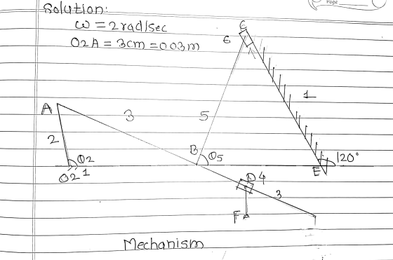
 Question 1 In the mechanism of figure Q1 crank O2A rotates at 70 revim rotational speed. Slider B slides on sliding link AC. T are as follows: O2A 6,0 cm, CD 10 cm, AB 2 cm, AC 8 cm, OsD 4 cm and O Angle θ2-1100 and θ5-100. Rotation) speed for 05 D:looney/ml Construct a velocity diagram for this position and t in clockwise about O2 at a constant he dimensions of the links of the mechanism [101 hen find...
2 The figure shows a mechanism consisting of a slider, attached to link 3 at B through a revolute...
 2 The figure shows a mechanism consisting of a slider, attached to link 3 at B through a revolute joint. Link 3 is attached to link 2 through a revolute joint at A. Link 2 is attached to the inertial frame through a revolute joint at O. Link 2 is 200 mm long and link 3 is 300 mm long. B is constrained to move in a slot angled at 40° to the horizontal. Initially, B is horizontally in line...
The planar four-bar mechanism shown below has a driving crank O1A that turns about O1 at...
 The planar four-bar mechanism shown below has a driving crank
O1A that turns about O1 at a constant rate of
(theta- dot) θ. = 10 rad/s CCW. The links O1A
and O2B are balanced and have a mass moments of inertia
about their center of mass of Iz = 0.02 kgm2 . The link
ABC has a center of mass located at point G, has a mass of m = 2
kg, and has a mass moment of inertia of...
The planar four-bar mechanism shown below has a driving crank
O1A that turns about O1 at a constant rate of
(theta- dot) θ. = 10 rad/s CCW. The links O1A
and O2B are balanced and have a mass moments of inertia
about their center of mass of Iz = 0.02 kgm2 . The link
ABC has a center of mass located at point G, has a mass of m = 2
kg, and has a mass moment of inertia of...
 Question 1 In the mechanism of figure Q1 crank O2A rotates at 70 revim rotational speed. Slider B slides on sliding link AC. T are as follows: O2A 6,0 cm, CD 10 cm, AB 2 cm, AC 8 cm, OsD 4 cm and O Angle θ2-1100 and θ5-100. Rotation) speed for 05 D:looney/ml Construct a velocity diagram for this position and t in clockwise about O2 at a constant he dimensions of the links of the mechanism [101 hen find...
 2 The figure shows a mechanism consisting of a slider, attached to link 3 at B through a revolute joint. Link 3 is attached to link 2 through a revolute joint at A. Link 2 is attached to the inertial frame through a revolute joint at O. Link 2 is 200 mm long and link 3 is 300 mm long. B is constrained to move in a slot angled at 40° to the horizontal. Initially, B is horizontally in line...
 The planar four-bar mechanism shown below has a driving crank
O1A that turns about O1 at a constant rate of
(theta- dot) θ. = 10 rad/s CCW. The links O1A
and O2B are balanced and have a mass moments of inertia
about their center of mass of Iz = 0.02 kgm2 . The link
ABC has a center of mass located at point G, has a mass of m = 2
kg, and has a mass moment of inertia of...
The planar four-bar mechanism shown below has a driving crank
O1A that turns about O1 at a constant rate of
(theta- dot) θ. = 10 rad/s CCW. The links O1A
and O2B are balanced and have a mass moments of inertia
about their center of mass of Iz = 0.02 kgm2 . The link
ABC has a center of mass located at point G, has a mass of m = 2
kg, and has a mass moment of inertia of...
Most questions answered within 3 hours.
-
Where is the error in this code sequence?
String s1 = "Hello";
String s2 = "ello";...
asked 11 months ago -
Financial data for Joel de Paris, Inc., for last year
follow:
Joel de Paris, Inc.
Balance...
asked 11 months ago -
Consider this reaction:
Al2(SO4)3 (aq)+ BaCl3
(aq) Al2Cl6 (aq)- +
3BaSO4(s) . What is the...
asked 11 months ago -
Suppose that Savneet is considering increasing her
recent random sample from 20 car rentals to 40...
asked 11 months ago -
Trucks arrive at an unloading terminal at an average rate of 120
per hour.
Trucks arrive...
asked 11 months ago -
Why are methanol and ethanol completely soluble in water while
octanol is not very little soluble....
asked 11 months ago -
A facilities manager at a university reads in a research report
that the mean amount of...
asked 11 months ago -
When the CuSO4 is rehydrated by adding water to the anhydrous
compound, is this an endothermic...
asked 11 months ago -
A ray of sunlight is passing from diamond into crown glass; the
angle of incidence is...
asked 11 months ago -
A block of mass 0.249 kg is placed on top of a light, vertical
spring of...
asked 11 months ago -
how do the kidneys compensate in the presences of acidosis
a) trigger hyperventilate
b) reserve acid...
asked 11 months ago -
Question 501 pts
The rental rate of capital to the firm increases. Which of the
following...
asked 11 months ago