The plane truss shown in Figure is composed of members having a square 15 mm × 15 mm cross section and modulus of elasticity E = 69 GPa.
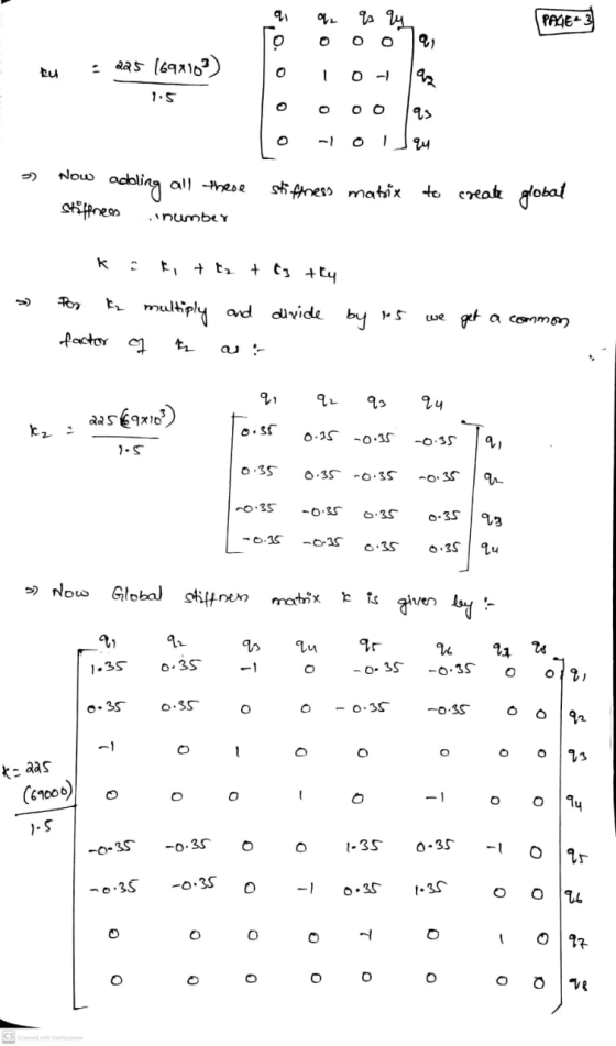
a. Assemble the global stiffness matrix.
b. Compute the nodal displacements in the global coordinate system for theloads shown.
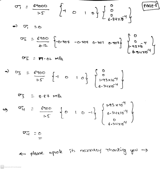
c. Compute the axial stress in each element

Homework Answers


![PAEN (6) Now displacenost matoix is given by T {a, 93 qu 95 26 27 28 w] 3 And also external force & matrix is given aut {FI f](http://img.homeworklib.com/questions/fd09b950-0b75-11eb-98e3-a51db8b68786.png?x-oss-process=image/resize,w_560)
Add Answer to:
The plane truss shown in Figure is composed of members having a
square 15 mm ×...
Figure Q5(a) shows a plane truss supported by a horizontal spring at the top node. The...
 Figure Q5(a) shows a plane truss supported by a horizontal spring at the top node. The truss members are of a solid circular cross section having a diameter of 20 mm and an elastic modulus (E) of 80 GPa (10° N/m2). The spring has a stiffness constant of k-2000 kN/m. A point load of 15 kN is applied at the top node. The direction of the load is indicated in the figure. The code numbers for elements, nodes, DOFS, and...
Please solve this question clearly and step by step. Thank you 2. A truss assembly shown...
 Please solve this question clearly and step by step.
Thank you
2. A truss assembly shown in Figure Q2 below is made of aluminum alloy that has a modulus of elasticity, E = 69 GPa. member is 225 mm2 The cross sectional area of each 4300 N (0, 40) m (40, 40) m 2 500 N 3 (0, 0) FIGURE Q2 Determine the global stiffness matrix for the truss assembly. a. [10 marks] Determine the displacement at node 3. b....
Please solve this question clearly and step by step.
Thank you
2. A truss assembly shown in Figure Q2 below is made of aluminum alloy that has a modulus of elasticity, E = 69 GPa. member is 225 mm2 The cross sectional area of each 4300 N (0, 40) m (40, 40) m 2 500 N 3 (0, 0) FIGURE Q2 Determine the global stiffness matrix for the truss assembly. a. [10 marks] Determine the displacement at node 3. b....
2. For the pin-jointed truss shown in Figure Q2.1 applied at node 4. The Young's modulus E(GPa) is the same for...
 2. For the pin-jointed truss shown in Figure Q2.1 applied at node 4. The Young's modulus E(GPa) is the same for the three truss vertical downward force P(kN) is a members. The cross sectional area of each of the truss members is indicated below and expressed in terms of a constant A. By using the stiffness method: (a) Compute the reduced stiffness matrix Kg [5 marks [10 marks (b) Calculate the global displacements of node 4 in terms of P,...
The plane truss is subjected to a load as shown in Figure 4. Take E = 200 GPa and cross sectional areas of members 1, 2...
 The plane truss is subjected to a load as shown in Figure 4. Take E = 200 GPa and cross sectional areas of members 1, 2 and 3 as 150, 250 and 200 mm2 respectively a) Assemble the upper triangular part of the global stiffness matrix for the truss b) Determine the horizontal and vertical displacements at node 4 c) Calculate the forces in each member of the truss. (25 marks) 20 kN 3 60° 4 1.5m 2 2 20m...
Solve the following truss problem. All truss members are ANSI 2x2x0.25 hollow square tubes (with rounded...
 Solve the following truss problem. All truss members are ANSI 2x2x0.25 hollow square tubes (with rounded corners) for which the cross-section area is A-1.5891 in2. The material has a modulus of E-29E6 psi. Length of element 1 and 5 is L-20 inches, and length of element 3 and 6 is 2L 40 inches. 7 5 6 P-1000 lb 2. 1. Solve in an Excel spreadsheet using the truss element. Note that there are only four different element stiffness matrices (look...
Question 4 The plane truss is subjected to a load as shown in Figure 4. Take E = 200 GPa and cross sectional areas of m...
 Question 4 The plane truss is subjected to a load as shown in Figure 4. Take E = 200 GPa and cross sectional areas of members 1, 2 and 3 as 150, 250 and 200 mm2 respectively a) Assemble the upper triangular part of the global stiffness matrix for the truss. b) Determine the horizontal and vertical displacements at node 4. c) Calculate the forces in each member of the truss. (25 marks) 20 kN 3 600 4 3 1.5m...
Plane truss
 The lower-right joint of the three-member plane truss shown in Figure 2 is supportedby a skew roller. The truss members are of a solid circular cross section having diameterd D 25 mm and elastic modulus E D 50 GPa. The force P D 70 kN is applied to theunconstrained joint. Number the nodes and elements, and solve for unknown nodaldisplacements and reaction forces using:a) Master-slave method,b) Penalty element method,c) Lagrange multiplier method.
Using the stiffness method, determine the axial forces within members and the displacements of jo...
 Using the stiffness method, determine the axial forces within
members and the displacements of joints of the truss shown in the
Figure 1. The truss was built using 50 mm x 50 mm x 3 mm SHS with
E= 200 GPa (approx). (Cross members BD and CE are not connected at
the middle)
(a) Show local stiffness matrices for each member and the
assembled global stiffness matrix. Show your step by step solution.
(30 Marks)
(b) Use an appropriate method...
Using the stiffness method, determine the axial forces within
members and the displacements of joints of the truss shown in the
Figure 1. The truss was built using 50 mm x 50 mm x 3 mm SHS with
E= 200 GPa (approx). (Cross members BD and CE are not connected at
the middle)
(a) Show local stiffness matrices for each member and the
assembled global stiffness matrix. Show your step by step solution.
(30 Marks)
(b) Use an appropriate method...
Question 1: For the plane (2D) truss shown below, evaluate the transformation matrix [T] and the stiffness matrix in the local axis system [KL] of all elements. Use these matrices to evaluate the ele...
 Question 1: For the plane (2D) truss shown below, evaluate the transformation matrix [T] and the stiffness matrix in the local axis system [KL] of all elements. Use these matrices to evaluate the element stiffness matrix in global axis system [KG] of the members and assembled them to generate the overall stiffness matrix [K of the truss. Modify the stiffness matrix [K] in order to incorporate boundary conditions following the elimination technique of rows and columns. Take E 200 GPa...
Finite Element Method 5.17 Displacements of the three-member truss shown are confined to the plane of...
 Finite Element Method
5.17 Displacements of the three-member truss shown are confined to the plane of the figure, and points 1, 2 and 3 are fixed to the stationary rim. All members have the same A, E, and L a) Obtain the 2x2 stiffness matrix that operates on the horizontal and vertical degrees of freedom of the central node. b) Obtain the corresponding global force vector c) Solve for the displacements and for axial stress in member (2-4), when the...
Finite Element Method
5.17 Displacements of the three-member truss shown are confined to the plane of the figure, and points 1, 2 and 3 are fixed to the stationary rim. All members have the same A, E, and L a) Obtain the 2x2 stiffness matrix that operates on the horizontal and vertical degrees of freedom of the central node. b) Obtain the corresponding global force vector c) Solve for the displacements and for axial stress in member (2-4), when the...
 Figure Q5(a) shows a plane truss supported by a horizontal spring at the top node. The truss members are of a solid circular cross section having a diameter of 20 mm and an elastic modulus (E) of 80 GPa (10° N/m2). The spring has a stiffness constant of k-2000 kN/m. A point load of 15 kN is applied at the top node. The direction of the load is indicated in the figure. The code numbers for elements, nodes, DOFS, and...
 Please solve this question clearly and step by step.
Thank you
2. A truss assembly shown in Figure Q2 below is made of aluminum alloy that has a modulus of elasticity, E = 69 GPa. member is 225 mm2 The cross sectional area of each 4300 N (0, 40) m (40, 40) m 2 500 N 3 (0, 0) FIGURE Q2 Determine the global stiffness matrix for the truss assembly. a. [10 marks] Determine the displacement at node 3. b....
Please solve this question clearly and step by step.
Thank you
2. A truss assembly shown in Figure Q2 below is made of aluminum alloy that has a modulus of elasticity, E = 69 GPa. member is 225 mm2 The cross sectional area of each 4300 N (0, 40) m (40, 40) m 2 500 N 3 (0, 0) FIGURE Q2 Determine the global stiffness matrix for the truss assembly. a. [10 marks] Determine the displacement at node 3. b....
 2. For the pin-jointed truss shown in Figure Q2.1 applied at node 4. The Young's modulus E(GPa) is the same for the three truss vertical downward force P(kN) is a members. The cross sectional area of each of the truss members is indicated below and expressed in terms of a constant A. By using the stiffness method: (a) Compute the reduced stiffness matrix Kg [5 marks [10 marks (b) Calculate the global displacements of node 4 in terms of P,...
 The plane truss is subjected to a load as shown in Figure 4. Take E = 200 GPa and cross sectional areas of members 1, 2 and 3 as 150, 250 and 200 mm2 respectively a) Assemble the upper triangular part of the global stiffness matrix for the truss b) Determine the horizontal and vertical displacements at node 4 c) Calculate the forces in each member of the truss. (25 marks) 20 kN 3 60° 4 1.5m 2 2 20m...
 Solve the following truss problem. All truss members are ANSI 2x2x0.25 hollow square tubes (with rounded corners) for which the cross-section area is A-1.5891 in2. The material has a modulus of E-29E6 psi. Length of element 1 and 5 is L-20 inches, and length of element 3 and 6 is 2L 40 inches. 7 5 6 P-1000 lb 2. 1. Solve in an Excel spreadsheet using the truss element. Note that there are only four different element stiffness matrices (look...
 Question 4 The plane truss is subjected to a load as shown in Figure 4. Take E = 200 GPa and cross sectional areas of members 1, 2 and 3 as 150, 250 and 200 mm2 respectively a) Assemble the upper triangular part of the global stiffness matrix for the truss. b) Determine the horizontal and vertical displacements at node 4. c) Calculate the forces in each member of the truss. (25 marks) 20 kN 3 600 4 3 1.5m...
 Using the stiffness method, determine the axial forces within
members and the displacements of joints of the truss shown in the
Figure 1. The truss was built using 50 mm x 50 mm x 3 mm SHS with
E= 200 GPa (approx). (Cross members BD and CE are not connected at
the middle)
(a) Show local stiffness matrices for each member and the
assembled global stiffness matrix. Show your step by step solution.
(30 Marks)
(b) Use an appropriate method...
Using the stiffness method, determine the axial forces within
members and the displacements of joints of the truss shown in the
Figure 1. The truss was built using 50 mm x 50 mm x 3 mm SHS with
E= 200 GPa (approx). (Cross members BD and CE are not connected at
the middle)
(a) Show local stiffness matrices for each member and the
assembled global stiffness matrix. Show your step by step solution.
(30 Marks)
(b) Use an appropriate method...
 Question 1: For the plane (2D) truss shown below, evaluate the transformation matrix [T] and the stiffness matrix in the local axis system [KL] of all elements. Use these matrices to evaluate the element stiffness matrix in global axis system [KG] of the members and assembled them to generate the overall stiffness matrix [K of the truss. Modify the stiffness matrix [K] in order to incorporate boundary conditions following the elimination technique of rows and columns. Take E 200 GPa...
 Finite Element Method
5.17 Displacements of the three-member truss shown are confined to the plane of the figure, and points 1, 2 and 3 are fixed to the stationary rim. All members have the same A, E, and L a) Obtain the 2x2 stiffness matrix that operates on the horizontal and vertical degrees of freedom of the central node. b) Obtain the corresponding global force vector c) Solve for the displacements and for axial stress in member (2-4), when the...
Finite Element Method
5.17 Displacements of the three-member truss shown are confined to the plane of the figure, and points 1, 2 and 3 are fixed to the stationary rim. All members have the same A, E, and L a) Obtain the 2x2 stiffness matrix that operates on the horizontal and vertical degrees of freedom of the central node. b) Obtain the corresponding global force vector c) Solve for the displacements and for axial stress in member (2-4), when the...
Most questions answered within 3 hours.
-
Where is the error in this code sequence?
String s1 = "Hello";
String s2 = "ello";...
asked 10 months ago -
Financial data for Joel de Paris, Inc., for last year
follow:
Joel de Paris, Inc.
Balance...
asked 10 months ago -
Consider this reaction:
Al2(SO4)3 (aq)+ BaCl3
(aq) Al2Cl6 (aq)- +
3BaSO4(s) . What is the...
asked 10 months ago -
Suppose that Savneet is considering increasing her
recent random sample from 20 car rentals to 40...
asked 10 months ago -
Trucks arrive at an unloading terminal at an average rate of 120
per hour.
Trucks arrive...
asked 10 months ago -
Why are methanol and ethanol completely soluble in water while
octanol is not very little soluble....
asked 10 months ago -
A facilities manager at a university reads in a research report
that the mean amount of...
asked 10 months ago -
When the CuSO4 is rehydrated by adding water to the anhydrous
compound, is this an endothermic...
asked 10 months ago -
A ray of sunlight is passing from diamond into crown glass; the
angle of incidence is...
asked 10 months ago -
A block of mass 0.249 kg is placed on top of a light, vertical
spring of...
asked 10 months ago -
how do the kidneys compensate in the presences of acidosis
a) trigger hyperventilate
b) reserve acid...
asked 10 months ago -
Question 501 pts
The rental rate of capital to the firm increases. Which of the
following...
asked 10 months ago