
Homework Answers
Solution-

To determine the maximum allowable force,we have to find out maximum allowable support reaction.

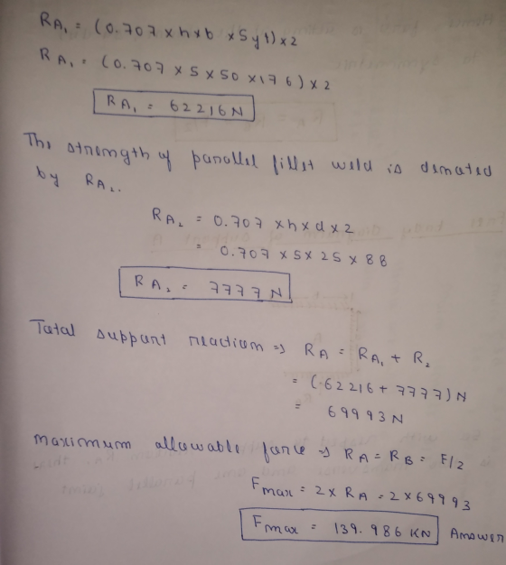
So,the maximum allowable force Fmax is finally found which is 2 x 69.993 = 139.986 KN
Add Answer to:
A long steel (SAE 1018HR) plate is welded on both ends as shown in the following...
A long steel (SAE 1018HR) plate is welded on both ends as shown in the following...
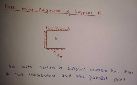
 A long steel (SAE 1018HR) plate is welded on both ends as shown in the following figure. The plate thickness is 10mm. The dimensions shown blow are b = 50mm, d = 25mm, c = 200mm, h = 5mm. A concentrated force F is applied at the center. The electrode material is E7010. A factor of safety is assumed to be 2.5 for both plate and welding. Find the maximum allowable force F. h va
A long steel (SAE 1018HR) plate is welded on both ends as shown in the following...
 A long steel (SAE 1018HR) plate is welded on both ends as shown in the following figure. The plate thickness is 10mm. The dimensions shown blow are b = 50mm, d = 25mm, c = 200mm, h = 5mm. A concentrated force F is applied at the center. The electrode material is E7010. A factor of safety is assumed to be 2.5 for both plate and welding. Find the maximum allowable force F. F enr d d b
A long steel (SAE 1018HR) plate is welded on both ends as shown in the following...
 A long steel (SAE 1018HR) plate is welded on both ends as shown in the following figure. The plate thickness is 10mm. The dimensions shown blow are b = 50mm,d = 25mm,c = 200mm, h = 5mm. A concentrated force F is applied at the center. The electrode material is E7010. A factor of safety is assumed to be 2.5 for both plate and welding. Find the maximum allowable force F. F О hv d ki b
A long steel (SAE 1018HR) plate is welded on both ends as shown in the following...
A long steel (SAE 1018HR) plate is welded on both ends as shown in the following figure. The plate thickness is 10mm. The dimensions shown blow are ? = 50??, ? = 25??, ? = 200??, ℎ = 5??. A concentrated force ? is applied at the center. The electrode material is E7010. A factor of safety is assumed to be 2.5 for both plate and welding. Find the maximum allowable force ?.
Can you please show me a detailed solution to this problem.? A long steel (SAE 1018HR)...
 Can you please show me a detailed solution to this problem.?
A long steel (SAE 1018HR) plate is welded on both ends as shown in the following figure. The plate thickness is 10mm. The dimensions shown blow are b = 50mm, d = 25mm, c = 200mm, h = 5mm. A concentrated force F is applied at the center. The electrode material is E7010. A factor of safety is assumed to be 2.5 for both plate and welding. Find the...
Can you please show me a detailed solution to this problem.?
A long steel (SAE 1018HR) plate is welded on both ends as shown in the following figure. The plate thickness is 10mm. The dimensions shown blow are b = 50mm, d = 25mm, c = 200mm, h = 5mm. A concentrated force F is applied at the center. The electrode material is E7010. A factor of safety is assumed to be 2.5 for both plate and welding. Find the...
Question 3 (20 marks) Two 304 stainless steel plates are welded together at their ends as...
 Question 3 (20 marks) Two 304 stainless steel plates are welded together at their ends as shown. During operation, the plates are exposed to a wet chloride environment and subjected to tensile forces as shown in Figure Q3. After a period of time, the plates are found to have failed at the weld joint as a result of stress corrosion cracking. weld 304 stainless steel plate 304 stainless steel plate applied force applied force Figure Q3 (a) Explain what is...
shown in Figure 2. Two circular disks A and B are welded to the ends of both bars. The disks lie in planes disks A a...
 shown in Figure 2. Two circular disks A and B are welded to the ends of both bars. The disks lie in planes disks A and B subjecting the bars to torsion. If the allowable maximum shear stress is 35 MPa and the allowable rate of twist is 3°/m for both bars, determine the smallest outer diameter (D, and Di) of both bars. The shear modulus of elasticity is 39 GPa to the axes of the bars. Forces 15 kN...
1. Complete the table below for the welded connection samples shown. ETNICES Ful enetration But Weld Partial Penet...
 1. Complete the table below for the welded connection samples shown. ETNICES Ful enetration But Weld Partial Penetration Burt Weld Flat/Plate Grade 300 Steel t>17 fyp 280 MPa up 440 MPa A-A B-B 10mm Weld Electrode: E48XX/W50X Quality: SP w480 MPa 1 Determine the nominal tension capacity of the welded connection as per AS4100 Nominal capacity is the design capacity without relevant capacity reduction factors Assume the design throat thickness can be taken to the full depth of penetration. 2...
i need clear and right solution pleaee. pleaes A steel plate of (0.5 in thickness) shown in the figure was fixed by four bolts of (0.5*13-UNC grade 4) to the vertical steel column of (0.6 in thick...
 i need clear and right solution pleaee.
pleaes
A steel plate of (0.5 in thickness) shown in the figure was fixed by four bolts of (0.5*13-UNC grade 4) to the vertical steel column of (0.6 in thickness) as shown in figure below. An inclined eccentric force F of 10 kips was subjected to the plate at point A. Calculate: (a) The maximum stress in the rivets. (b) Check the safety factor if the plate and wall have a tensile strength...
i need clear and right solution pleaee.
pleaes
A steel plate of (0.5 in thickness) shown in the figure was fixed by four bolts of (0.5*13-UNC grade 4) to the vertical steel column of (0.6 in thickness) as shown in figure below. An inclined eccentric force F of 10 kips was subjected to the plate at point A. Calculate: (a) The maximum stress in the rivets. (b) Check the safety factor if the plate and wall have a tensile strength...
A reciprocating pump weighing W-150 lb, is mounted at a middle of a steel plate of thickness 0.5 ...
 A reciprocating pump weighing W-150 lb, is mounted at a middle of a steel plate of thickness 0.5 in., width of 20 in., and clamped along two edges as shown. During operation of pump, the plate is subjected to a harmonic force F(t)-P, . cos(ω·) [lb] 0.5 in. 100 in. where the amplitude of harmonic force is Fo=50 lb and its angular frequency: ω-62832 radl s Model the system as a simple spring and mass system in the horizontal plane....
 A long steel (SAE 1018HR) plate is welded on both ends as shown in the following figure. The plate thickness is 10mm. The dimensions shown blow are b = 50mm, d = 25mm, c = 200mm, h = 5mm. A concentrated force F is applied at the center. The electrode material is E7010. A factor of safety is assumed to be 2.5 for both plate and welding. Find the maximum allowable force F. h va
 A long steel (SAE 1018HR) plate is welded on both ends as shown in the following figure. The plate thickness is 10mm. The dimensions shown blow are b = 50mm, d = 25mm, c = 200mm, h = 5mm. A concentrated force F is applied at the center. The electrode material is E7010. A factor of safety is assumed to be 2.5 for both plate and welding. Find the maximum allowable force F. F enr d d b
 A long steel (SAE 1018HR) plate is welded on both ends as shown in the following figure. The plate thickness is 10mm. The dimensions shown blow are b = 50mm,d = 25mm,c = 200mm, h = 5mm. A concentrated force F is applied at the center. The electrode material is E7010. A factor of safety is assumed to be 2.5 for both plate and welding. Find the maximum allowable force F. F О hv d ki b
 Can you please show me a detailed solution to this problem.?
A long steel (SAE 1018HR) plate is welded on both ends as shown in the following figure. The plate thickness is 10mm. The dimensions shown blow are b = 50mm, d = 25mm, c = 200mm, h = 5mm. A concentrated force F is applied at the center. The electrode material is E7010. A factor of safety is assumed to be 2.5 for both plate and welding. Find the...
Can you please show me a detailed solution to this problem.?
A long steel (SAE 1018HR) plate is welded on both ends as shown in the following figure. The plate thickness is 10mm. The dimensions shown blow are b = 50mm, d = 25mm, c = 200mm, h = 5mm. A concentrated force F is applied at the center. The electrode material is E7010. A factor of safety is assumed to be 2.5 for both plate and welding. Find the...
 Question 3 (20 marks) Two 304 stainless steel plates are welded together at their ends as shown. During operation, the plates are exposed to a wet chloride environment and subjected to tensile forces as shown in Figure Q3. After a period of time, the plates are found to have failed at the weld joint as a result of stress corrosion cracking. weld 304 stainless steel plate 304 stainless steel plate applied force applied force Figure Q3 (a) Explain what is...
 shown in Figure 2. Two circular disks A and B are welded to the ends of both bars. The disks lie in planes disks A and B subjecting the bars to torsion. If the allowable maximum shear stress is 35 MPa and the allowable rate of twist is 3°/m for both bars, determine the smallest outer diameter (D, and Di) of both bars. The shear modulus of elasticity is 39 GPa to the axes of the bars. Forces 15 kN...
 1. Complete the table below for the welded connection samples shown. ETNICES Ful enetration But Weld Partial Penetration Burt Weld Flat/Plate Grade 300 Steel t>17 fyp 280 MPa up 440 MPa A-A B-B 10mm Weld Electrode: E48XX/W50X Quality: SP w480 MPa 1 Determine the nominal tension capacity of the welded connection as per AS4100 Nominal capacity is the design capacity without relevant capacity reduction factors Assume the design throat thickness can be taken to the full depth of penetration. 2...
 i need clear and right solution pleaee.
pleaes
A steel plate of (0.5 in thickness) shown in the figure was fixed by four bolts of (0.5*13-UNC grade 4) to the vertical steel column of (0.6 in thickness) as shown in figure below. An inclined eccentric force F of 10 kips was subjected to the plate at point A. Calculate: (a) The maximum stress in the rivets. (b) Check the safety factor if the plate and wall have a tensile strength...
i need clear and right solution pleaee.
pleaes
A steel plate of (0.5 in thickness) shown in the figure was fixed by four bolts of (0.5*13-UNC grade 4) to the vertical steel column of (0.6 in thickness) as shown in figure below. An inclined eccentric force F of 10 kips was subjected to the plate at point A. Calculate: (a) The maximum stress in the rivets. (b) Check the safety factor if the plate and wall have a tensile strength...
 A reciprocating pump weighing W-150 lb, is mounted at a middle of a steel plate of thickness 0.5 in., width of 20 in., and clamped along two edges as shown. During operation of pump, the plate is subjected to a harmonic force F(t)-P, . cos(ω·) [lb] 0.5 in. 100 in. where the amplitude of harmonic force is Fo=50 lb and its angular frequency: ω-62832 radl s Model the system as a simple spring and mass system in the horizontal plane....
Most questions answered within 3 hours.
-
Where is the error in this code sequence?
String s1 = "Hello";
String s2 = "ello";...
asked 11 months ago -
Financial data for Joel de Paris, Inc., for last year
follow:
Joel de Paris, Inc.
Balance...
asked 11 months ago -
Consider this reaction:
Al2(SO4)3 (aq)+ BaCl3
(aq) Al2Cl6 (aq)- +
3BaSO4(s) . What is the...
asked 11 months ago -
Suppose that Savneet is considering increasing her
recent random sample from 20 car rentals to 40...
asked 11 months ago -
Trucks arrive at an unloading terminal at an average rate of 120
per hour.
Trucks arrive...
asked 11 months ago -
Why are methanol and ethanol completely soluble in water while
octanol is not very little soluble....
asked 11 months ago -
A facilities manager at a university reads in a research report
that the mean amount of...
asked 11 months ago -
When the CuSO4 is rehydrated by adding water to the anhydrous
compound, is this an endothermic...
asked 11 months ago -
A ray of sunlight is passing from diamond into crown glass; the
angle of incidence is...
asked 11 months ago -
A block of mass 0.249 kg is placed on top of a light, vertical
spring of...
asked 11 months ago -
how do the kidneys compensate in the presences of acidosis
a) trigger hyperventilate
b) reserve acid...
asked 11 months ago -
Question 501 pts
The rental rate of capital to the firm increases. Which of the
following...
asked 11 months ago