
Homework Answers


Add Answer to:
A long steel (SAE 1018HR) plate is welded on both ends as shown in the following...
A long steel (SAE 1018HR) plate is welded on both ends as shown in the following...
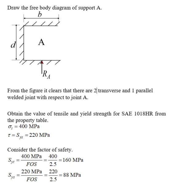
 A long steel (SAE 1018HR) plate is welded on both ends as shown in the following figure. The plate thickness is 10mm. The dimensions shown blow are b = 50mm, d 25mm, c = 200mm, h = 5mm. A concentrated force F is applied at the center. The electrode material is E7010. A factor of safety is assumed to be 2.5 for both plate and welding. Find the maximum allowable force F. F wall *** b
A long steel (SAE 1018HR) plate is welded on both ends as shown in the following...
 A long steel (SAE 1018HR) plate is welded on both ends as shown in the following figure. The plate thickness is 10mm. The dimensions shown blow are b = 50mm, d = 25mm, c = 200mm, h = 5mm. A concentrated force F is applied at the center. The electrode material is E7010. A factor of safety is assumed to be 2.5 for both plate and welding. Find the maximum allowable force F. F enr d d b
A long steel (SAE 1018HR) plate is welded on both ends as shown in the following...
 A long steel (SAE 1018HR) plate is welded on both ends as shown in the following figure. The plate thickness is 10mm. The dimensions shown blow are b = 50mm,d = 25mm,c = 200mm, h = 5mm. A concentrated force F is applied at the center. The electrode material is E7010. A factor of safety is assumed to be 2.5 for both plate and welding. Find the maximum allowable force F. F О hv d ki b
Can you please show me a detailed solution to this problem.? A long steel (SAE 1018HR)...
 Can you please show me a detailed solution to this problem.?
A long steel (SAE 1018HR) plate is welded on both ends as shown in the following figure. The plate thickness is 10mm. The dimensions shown blow are b = 50mm, d = 25mm, c = 200mm, h = 5mm. A concentrated force F is applied at the center. The electrode material is E7010. A factor of safety is assumed to be 2.5 for both plate and welding. Find the...
Can you please show me a detailed solution to this problem.?
A long steel (SAE 1018HR) plate is welded on both ends as shown in the following figure. The plate thickness is 10mm. The dimensions shown blow are b = 50mm, d = 25mm, c = 200mm, h = 5mm. A concentrated force F is applied at the center. The electrode material is E7010. A factor of safety is assumed to be 2.5 for both plate and welding. Find the...
A long steel (SAE 1018HR) plate is welded on both ends as shown in the following...
A long steel (SAE 1018HR) plate is welded on both ends as shown in the following figure. The plate thickness is 10mm. The dimensions shown blow are ? = 50??, ? = 25??, ? = 200??, ℎ = 5??. A concentrated force ? is applied at the center. The electrode material is E7010. A factor of safety is assumed to be 2.5 for both plate and welding. Find the maximum allowable force ?.
A reciprocating pump weighing W-150 lb, is mounted at a middle of a steel plate of thickness 0.5 ...
 A reciprocating pump weighing W-150 lb, is mounted at a middle of a steel plate of thickness 0.5 in., width of 20 in., and clamped along two edges as shown. During operation of pump, the plate is subjected to a harmonic force F(t)-P, . cos(ω·) [lb] 0.5 in. 100 in. where the amplitude of harmonic force is Fo=50 lb and its angular frequency: ω-62832 radl s Model the system as a simple spring and mass system in the horizontal plane....
A reciprocating pump weighing W-150 lb, is mounted at a middle of a steel plate of thickness 0.5 ...
 A reciprocating pump weighing W-150 lb, is mounted at a middle of a steel plate of thickness 0.5 in., width of 20 in., and clamped along two edges as shown. During operation of pump, the plate is subjected to a harmonic force Ft)-Fo.t) ibl. 0.5 in. Fio),x(t) 100 in. where the amplitude of harmonic force is F俨50 lh and its angular frequency: 62.832 radls Model the system as a simple spring and mass system in the horizontal plane. The mass...
Auge Steel Framing Details 1. Complete all light g auge steel componente ir the following wall se...
 auge Steel Framing Details 1. Complete all light g auge steel componente ir the following wall section, including floor joists, wall studs, roof rafters, and required clips angles, stiffeners, and fasteners. Label all components. Roof sheathing Wall sheathing 。 Interior wallboard Subflooring Foundation 103 Scale: l square =2" (50 mm) Name: necessity of cutting holes in m on the construction ste 12.11. 12.15). Thack etions a sed for top and bottom plates, e construction, shemperature that col tural shapes. Prers...
Consider a cylindrical capacitor like that shown in Fig. 24.6. Let d = rb − ra...
 Consider a cylindrical capacitor like that shown in Fig. 24.6. Let d = rb − ra be the spacing between the inner and outer conductors. (a) Let the radii of the two conductors be only slightly different, so that d << ra. Show that the result derived in Example 24.4 (Section 24.1) for the capacitance of a cylindrical capacitor then reduces to Eq. (24.2), the equation for the capacitance of a parallel-plate capacitor, with A being the surface area of...
 A long steel (SAE 1018HR) plate is welded on both ends as shown in the following figure. The plate thickness is 10mm. The dimensions shown blow are b = 50mm, d 25mm, c = 200mm, h = 5mm. A concentrated force F is applied at the center. The electrode material is E7010. A factor of safety is assumed to be 2.5 for both plate and welding. Find the maximum allowable force F. F wall *** b
 A long steel (SAE 1018HR) plate is welded on both ends as shown in the following figure. The plate thickness is 10mm. The dimensions shown blow are b = 50mm, d = 25mm, c = 200mm, h = 5mm. A concentrated force F is applied at the center. The electrode material is E7010. A factor of safety is assumed to be 2.5 for both plate and welding. Find the maximum allowable force F. F enr d d b
 A long steel (SAE 1018HR) plate is welded on both ends as shown in the following figure. The plate thickness is 10mm. The dimensions shown blow are b = 50mm,d = 25mm,c = 200mm, h = 5mm. A concentrated force F is applied at the center. The electrode material is E7010. A factor of safety is assumed to be 2.5 for both plate and welding. Find the maximum allowable force F. F О hv d ki b
 Can you please show me a detailed solution to this problem.?
A long steel (SAE 1018HR) plate is welded on both ends as shown in the following figure. The plate thickness is 10mm. The dimensions shown blow are b = 50mm, d = 25mm, c = 200mm, h = 5mm. A concentrated force F is applied at the center. The electrode material is E7010. A factor of safety is assumed to be 2.5 for both plate and welding. Find the...
Can you please show me a detailed solution to this problem.?
A long steel (SAE 1018HR) plate is welded on both ends as shown in the following figure. The plate thickness is 10mm. The dimensions shown blow are b = 50mm, d = 25mm, c = 200mm, h = 5mm. A concentrated force F is applied at the center. The electrode material is E7010. A factor of safety is assumed to be 2.5 for both plate and welding. Find the...
 A reciprocating pump weighing W-150 lb, is mounted at a middle of a steel plate of thickness 0.5 in., width of 20 in., and clamped along two edges as shown. During operation of pump, the plate is subjected to a harmonic force F(t)-P, . cos(ω·) [lb] 0.5 in. 100 in. where the amplitude of harmonic force is Fo=50 lb and its angular frequency: ω-62832 radl s Model the system as a simple spring and mass system in the horizontal plane....
 A reciprocating pump weighing W-150 lb, is mounted at a middle of a steel plate of thickness 0.5 in., width of 20 in., and clamped along two edges as shown. During operation of pump, the plate is subjected to a harmonic force Ft)-Fo.t) ibl. 0.5 in. Fio),x(t) 100 in. where the amplitude of harmonic force is F俨50 lh and its angular frequency: 62.832 radls Model the system as a simple spring and mass system in the horizontal plane. The mass...
 auge Steel Framing Details 1. Complete all light g auge steel componente ir the following wall section, including floor joists, wall studs, roof rafters, and required clips angles, stiffeners, and fasteners. Label all components. Roof sheathing Wall sheathing 。 Interior wallboard Subflooring Foundation 103 Scale: l square =2" (50 mm) Name: necessity of cutting holes in m on the construction ste 12.11. 12.15). Thack etions a sed for top and bottom plates, e construction, shemperature that col tural shapes. Prers...
 Consider a cylindrical capacitor like that shown in Fig. 24.6. Let d = rb − ra be the spacing between the inner and outer conductors. (a) Let the radii of the two conductors be only slightly different, so that d << ra. Show that the result derived in Example 24.4 (Section 24.1) for the capacitance of a cylindrical capacitor then reduces to Eq. (24.2), the equation for the capacitance of a parallel-plate capacitor, with A being the surface area of...
Most questions answered within 3 hours.
-
Where is the error in this code sequence?
String s1 = "Hello";
String s2 = "ello";...
asked 11 months ago -
Financial data for Joel de Paris, Inc., for last year
follow:
Joel de Paris, Inc.
Balance...
asked 11 months ago -
Consider this reaction:
Al2(SO4)3 (aq)+ BaCl3
(aq) Al2Cl6 (aq)- +
3BaSO4(s) . What is the...
asked 11 months ago -
Suppose that Savneet is considering increasing her
recent random sample from 20 car rentals to 40...
asked 11 months ago -
Trucks arrive at an unloading terminal at an average rate of 120
per hour.
Trucks arrive...
asked 11 months ago -
Why are methanol and ethanol completely soluble in water while
octanol is not very little soluble....
asked 11 months ago -
A facilities manager at a university reads in a research report
that the mean amount of...
asked 11 months ago -
When the CuSO4 is rehydrated by adding water to the anhydrous
compound, is this an endothermic...
asked 11 months ago -
A ray of sunlight is passing from diamond into crown glass; the
angle of incidence is...
asked 11 months ago -
A block of mass 0.249 kg is placed on top of a light, vertical
spring of...
asked 11 months ago -
how do the kidneys compensate in the presences of acidosis
a) trigger hyperventilate
b) reserve acid...
asked 11 months ago -
Question 501 pts
The rental rate of capital to the firm increases. Which of the
following...
asked 11 months ago