
Homework Answers

Add Answer to:
A cone clutch is to be designed to transmit 7.5 kW at 900 r.p.m. The cone...
3. A single plate clutch, effective on both sides, is required to transmit 25 kW at...
 3. A single plate clutch, effective on both sides, is required to transmit 25 kW at 3000 r.p.m. Determine the outer and inner radii of frictional surface if the coefficient of friction is 0.255, the ratio of radii is 1.25 and the maximum pressure is not to exceed 0.1 N/mm². Also determine the axial thrust to be provided by springs. Assume the theory of uniform wear. (2 marks)
1. A multiple friction clutch is required to transmit 89.52 kW at 3000 rpm. The plates...
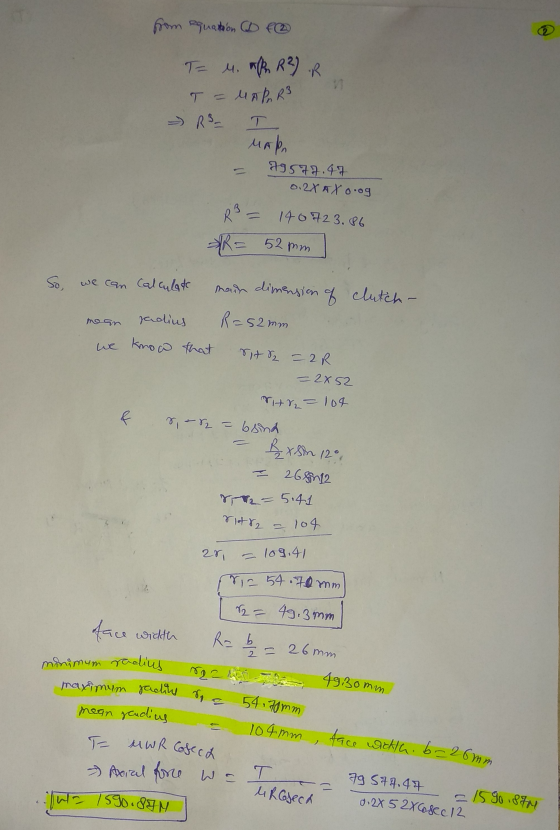
 1. A multiple friction clutch is required to transmit 89.52 kW at 3000 rpm. The plates are alternatively of steel and phosphor bronze and they run in oil. The coefficient of friction is 0.08. The internal radius of the friction surface is 0.8 times the radius of the external surface. The axial pressure is limited to 20 x 104 N/m2. If the maximum diameter of the frictional surface is not to exceed 250 mm, determine the number of plates required.
A two stage reduction drive is to be designed to transmit 2 kW; the input speed...
 A two stage reduction drive is to be designed to transmit 2 kW; the input speed being 960 r.p.m. and overall reduction ratio being 9. The drive consists of straight tooth spur gears only, the shafts being spaced 200 mm apart, the input and output shafts being co-axial. (a) Draw a layout of a suitable system to meet the above specifications, indicating the speeds of all rotating components. (6) Calculate the module, pitch diameter, number of teeth, blank diameter and...
Pitch, P Thrust collar Equal Figure 3 (20%) As shown in Figure 4, a cone clutch...
 Pitch, P Thrust collar Equal Figure 3 (20%) As shown in Figure 4, a cone clutch of inclination 10° is to carry 35 kW at 800 rpm. Th width of the lining along an element of the cone is 55 mm. Maximum lining pressure is to be 0 MPa. The coefficient of friction is 0.2. Find suitable values for ro and ri Splined
A pair of bevel gears is required to transmit 11 kW at 500 r.p.m. from the motor shaft to another...
A pair of bevel gears is required to transmit 11 kW at 500 r.p.m. from the motor shaft to another shaft, the speed reduction being 3 : 1. The shafts are inclined at 60º. The pinion is to have 24 teeth with a pressure angle of 20º and is to be made of cast steel having a static stress of 80 MPa. The gear is to be made of cast iron with a static stress of 55 MPa. The tooth...
A-V belt is to transmit 20 kW from a 250 mm pitch diameter sheave to a...
 A-V belt is to transmit 20 kW from a 250 mm pitch diameter sheave to a 900 mm diameter pulley. The center distance between the two shafts is 1000 mm. The groove angle is 40' and the coefficient of friction for the belt and sheave is 0.2 and the coefficient of friction between the belt and flat pulley is 0.2. The cross-section of the belt is 40 mm wide at the top, 20 mm wide at the bottom and 25...
Q2. Written assignment: A flat belt is required to transmit (35 kW) from a pulley of...
 Q2. Written assignment: A flat belt is required to transmit (35 kW) from a pulley of (1.5 m) effective diameter running at (320 RPM). The angle of contact is spread over (11/24) of the circumference. The coefficient of friction between the belt and pulley surface is (0.3). Determine, taking centrifugal tension into account, width of the belt required. It is given that the belt thickness is (9.5 mm), density of its material is (1100 kg/m²) and the related permissible working...
Figure 1 shows the layout of countershaft used to transmit power to a blower through a...
 Figure 1 shows the layout of countershaft used to transmit power to a blower through a pulley drive (4-5). Pulley (driving sheave) 4 has a diameter of 125-mm and pulley (driven sheave) 5 has a diameter of 75 mm. Pulley 5 is mounted vertically below pulley 4 (as shown in the figure). Belt tension on the loose side is 20% of the tension on the tight side. A power of 7.5 kW is transmitted via the gear set (2-3) from...
summarizr the followung info and write them in your own words and break them into different...
summarizr the followung info and write them in your own words and break them into different key points. 6.5 Metering Chamber: 6.5.1 The minimum size of the metering box is governed by the metering area required to obtain a representative test area for the specimen (see 7.2) and for maintenance of reasonable test accuracy. For example, for specimens incorporating air spaces or stud spaces, the metering area shall span an integral number of spaces (see 5.5). The depth of...
summatize the following info and break them into differeng key points. write them in yojr own...
 summatize the following info and break them into differeng key points. write them in yojr own words
apartus
6.1 Introduction—The design of a successful hot box appa- ratus is influenced by many factors. Before beginning the design of an apparatus meeting this standard, the designer shall review the discussion on the limitations and accuracy, Section 13, discussions of the energy flows in a hot box, Annex A2, the metering box wall loss flow, Annex A3, and flanking loss, Annex...
summatize the following info and break them into differeng key points. write them in yojr own words
apartus
6.1 Introduction—The design of a successful hot box appa- ratus is influenced by many factors. Before beginning the design of an apparatus meeting this standard, the designer shall review the discussion on the limitations and accuracy, Section 13, discussions of the energy flows in a hot box, Annex A2, the metering box wall loss flow, Annex A3, and flanking loss, Annex...
 3. A single plate clutch, effective on both sides, is required to transmit 25 kW at 3000 r.p.m. Determine the outer and inner radii of frictional surface if the coefficient of friction is 0.255, the ratio of radii is 1.25 and the maximum pressure is not to exceed 0.1 N/mm². Also determine the axial thrust to be provided by springs. Assume the theory of uniform wear. (2 marks)
 1. A multiple friction clutch is required to transmit 89.52 kW at 3000 rpm. The plates are alternatively of steel and phosphor bronze and they run in oil. The coefficient of friction is 0.08. The internal radius of the friction surface is 0.8 times the radius of the external surface. The axial pressure is limited to 20 x 104 N/m2. If the maximum diameter of the frictional surface is not to exceed 250 mm, determine the number of plates required.
 A two stage reduction drive is to be designed to transmit 2 kW; the input speed being 960 r.p.m. and overall reduction ratio being 9. The drive consists of straight tooth spur gears only, the shafts being spaced 200 mm apart, the input and output shafts being co-axial. (a) Draw a layout of a suitable system to meet the above specifications, indicating the speeds of all rotating components. (6) Calculate the module, pitch diameter, number of teeth, blank diameter and...
 Pitch, P Thrust collar Equal Figure 3 (20%) As shown in Figure 4, a cone clutch of inclination 10° is to carry 35 kW at 800 rpm. Th width of the lining along an element of the cone is 55 mm. Maximum lining pressure is to be 0 MPa. The coefficient of friction is 0.2. Find suitable values for ro and ri Splined
 A-V belt is to transmit 20 kW from a 250 mm pitch diameter sheave to a 900 mm diameter pulley. The center distance between the two shafts is 1000 mm. The groove angle is 40' and the coefficient of friction for the belt and sheave is 0.2 and the coefficient of friction between the belt and flat pulley is 0.2. The cross-section of the belt is 40 mm wide at the top, 20 mm wide at the bottom and 25...
 Q2. Written assignment: A flat belt is required to transmit (35 kW) from a pulley of (1.5 m) effective diameter running at (320 RPM). The angle of contact is spread over (11/24) of the circumference. The coefficient of friction between the belt and pulley surface is (0.3). Determine, taking centrifugal tension into account, width of the belt required. It is given that the belt thickness is (9.5 mm), density of its material is (1100 kg/m²) and the related permissible working...
 Figure 1 shows the layout of countershaft used to transmit power to a blower through a pulley drive (4-5). Pulley (driving sheave) 4 has a diameter of 125-mm and pulley (driven sheave) 5 has a diameter of 75 mm. Pulley 5 is mounted vertically below pulley 4 (as shown in the figure). Belt tension on the loose side is 20% of the tension on the tight side. A power of 7.5 kW is transmitted via the gear set (2-3) from...
 summatize the following info and break them into differeng key points. write them in yojr own words
apartus
6.1 Introduction—The design of a successful hot box appa- ratus is influenced by many factors. Before beginning the design of an apparatus meeting this standard, the designer shall review the discussion on the limitations and accuracy, Section 13, discussions of the energy flows in a hot box, Annex A2, the metering box wall loss flow, Annex A3, and flanking loss, Annex...
summatize the following info and break them into differeng key points. write them in yojr own words
apartus
6.1 Introduction—The design of a successful hot box appa- ratus is influenced by many factors. Before beginning the design of an apparatus meeting this standard, the designer shall review the discussion on the limitations and accuracy, Section 13, discussions of the energy flows in a hot box, Annex A2, the metering box wall loss flow, Annex A3, and flanking loss, Annex...
Most questions answered within 3 hours.
-
Where is the error in this code sequence?
String s1 = "Hello";
String s2 = "ello";...
asked 11 months ago -
Financial data for Joel de Paris, Inc., for last year
follow:
Joel de Paris, Inc.
Balance...
asked 11 months ago -
Consider this reaction:
Al2(SO4)3 (aq)+ BaCl3
(aq) Al2Cl6 (aq)- +
3BaSO4(s) . What is the...
asked 11 months ago -
Suppose that Savneet is considering increasing her
recent random sample from 20 car rentals to 40...
asked 11 months ago -
Trucks arrive at an unloading terminal at an average rate of 120
per hour.
Trucks arrive...
asked 11 months ago -
Why are methanol and ethanol completely soluble in water while
octanol is not very little soluble....
asked 11 months ago -
A facilities manager at a university reads in a research report
that the mean amount of...
asked 11 months ago -
When the CuSO4 is rehydrated by adding water to the anhydrous
compound, is this an endothermic...
asked 11 months ago -
A ray of sunlight is passing from diamond into crown glass; the
angle of incidence is...
asked 11 months ago -
A block of mass 0.249 kg is placed on top of a light, vertical
spring of...
asked 11 months ago -
how do the kidneys compensate in the presences of acidosis
a) trigger hyperventilate
b) reserve acid...
asked 11 months ago -
Question 501 pts
The rental rate of capital to the firm increases. Which of the
following...
asked 11 months ago
> In answer #1 there is an error on the calculation of R. it must be R^3=1407238.634 and not R^3=140723.86
Clifford kapembwa Fri, Jan 7, 2022 11:37 PM