Homework Answers
Add Answer to:
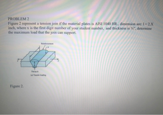
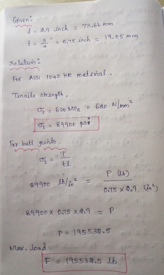
Figure 2 represent a tension join if the material plates is
AISI 1040 HR., dimension are:...
4. (a) Design a bolted joint to join the two members shown in the figure below. Specify the number of bolts, the pattern, the bolt grade, and the bolt size 8 x4 x 12 Box sect 4 in 6in 0.50 in ty...
 4. (a) Design a bolted joint to join the two members shown in the figure below. Specify the number of bolts, the pattern, the bolt grade, and the bolt size 8 x4 x 12 Box sect 4 in 6in 0.50 in typical 0.50 plate 12 000 lb P (b). Two steel plates are joined using 3/8-inch parallel-loaded fillet welds. The yield strength, Sy, and the length of the welds are known. The design factor is 3.5. Determine the maximum tensile...
The cold-drawn AISI 1040 steel bar shown in the figure is subjected to a completely reversed axial load fluctuating between 28 kN in compression to 28 kN in tension. Estimate the fatigue factor of safety based on achieving infinite life and the yielding f
 The cold-drawn AISI 1040 steel bar shown in the figure is subjected to a completely reversed axial load fluctuating between 28 kN in compression to 28 kN in tension. Estimate the fatigue factor of safety based on achieving infinite life and the yielding factor of safety. If infinite life is not predicted, estimate the number of cycles to failure.
5 Part 2 of 3 Required information The cold-drawn AISI 1040 steel bar shown in the...
 5 Part 2 of 3 Required information The cold-drawn AISI 1040 steel bar shown in the figure is subjected to a completely reversed axial load fluctuating between 16 kN in compression to 16 kN in tension Estimate the fatigue factor of safety based on achieving infinite life and the yielding factor of safety. If infinite life is not predicted, estimate the number of cycles to failure 0:58:22 Files 10 What is the factor of safety against fatigue? The factor of...
AISI 1018 HR Section #2 (80p) 035 CD 1018 HR Q1. The figure shows a shaft...
 AISI 1018 HR
Section #2 (80p) 035 CD 1018 HR Q1. The figure shows a shaft mounted in bearings at A and D and having pulleys at B and C. The forces shown acting on the pulley surfaces represent the belt tensions. The shaft is to be made of AISI 1035 CD steel. Using both conservative failure theory and distortion energy theory with a design factor of 2.5, determine the minimum shaft diameter to avoid yielding. dete n-2.5 127lbt 8y=61&...
AISI 1018 HR
Section #2 (80p) 035 CD 1018 HR Q1. The figure shows a shaft mounted in bearings at A and D and having pulleys at B and C. The forces shown acting on the pulley surfaces represent the belt tensions. The shaft is to be made of AISI 1035 CD steel. Using both conservative failure theory and distortion energy theory with a design factor of 2.5, determine the minimum shaft diameter to avoid yielding. dete n-2.5 127lbt 8y=61&...
2. Figure 2 below shows a crank loaded by a force F. The material used for...
 2. Figure 2 below shows a crank loaded by a force F. The material used for the crank is steel AISI 4142, and its yield stress is 235 kpsi. Determine the critical load F by using the following different failure theories (assume factor of safety n-2): a. Maximum normal stress theory (MNS); b. Maximum shear stress theory (MSS); c. Distortion-energy theory (DE). Figure 2. A crank under a force F
2. A rectangular beam, 400 x 600 mm gross dimension, is cast using a concrete strength...
 2. A rectangular beam, 400 x 600 mm gross dimension, is cast using a concrete strength of fc 30 MPa, reinforced with 5-25 mm diameter steel bar at the effective depth of 500 mm. If is subjected to a moment, M 130 kN-m. Determine the following: Magnitude of the bending moment that cracks the singly-reinforced beam section. (10 pts) b. For the computed cracking moment, determine the maximum compressive stress in the concrete and the stress in the tension steel....
Question 1 (30 Marks) Plate A is fillet-welded to Plate B as shown in Figure 1. Plate A and Plate B have the same material properties Both plates are 10 mm thick. There are two holes (with a diameter...
 Question 1 (30 Marks) Plate A is fillet-welded to Plate B as shown in Figure 1. Plate A and Plate B have the same material properties Both plates are 10 mm thick. There are two holes (with a diameter of d) in Plate A. It is assumed that weld failure will not occur (a) If Plate A has a yield stress (fy) of 350 MPa and an ultimate tensile strength (fu) of 450 MPa, what is the maximum load (P)...
2.The shaft shown in the figure is driven by a gear at the right keyways, drive...
 2.The shaft shown in the figure is driven by a gear at the right keyways, drive a fan at eh left keyways, and supported by two deep grove ball bearings. The shaft is made of AISI 1020 cold- drawn steel. At steady state speed, the gear transmits a radial load of 230 Ibf and a tangential load of 633 Ibf at pitch diameter of 8 inch. Determine fatigue factor of safety at any potentially critical locations using the DE-Gerber failure...
2. A beam is composed of two IPE 100 steel sections as shown in the figure....
 2. A beam is composed of two IPE 100 steel sections as shown in the figure. To increase its strength, it is proposed that two steel plates of thickness 8 mm be added at its top and bottom flanges. a) Determine the support reactions. b) Draw shear force and bending moment diagrams. c) If the allowable bending stress of the beam is 300 MPa determine the required width d of the plates to safely support the load. (Use Imar =...
The cantilevered bar in the figure is made from a ductile material and is statically loaded...
 The cantilevered bar in the figure is made from a ductile material and is statically loaded with Fx-320 lbf, Fy = 255 lbf, and F- 105 lbf. The critical stress element experiences = 58.4 kpsi, σ x ,axial =0.407 kpsi and τ = 15.6 kpsi. Determine the minimum factor of safety for fatigue at point A, based on infinite life. If the life is not infinite, estimate the number of cycles. The force F is applied as a repeated load...
 4. (a) Design a bolted joint to join the two members shown in the figure below. Specify the number of bolts, the pattern, the bolt grade, and the bolt size 8 x4 x 12 Box sect 4 in 6in 0.50 in typical 0.50 plate 12 000 lb P (b). Two steel plates are joined using 3/8-inch parallel-loaded fillet welds. The yield strength, Sy, and the length of the welds are known. The design factor is 3.5. Determine the maximum tensile...
 5 Part 2 of 3 Required information The cold-drawn AISI 1040 steel bar shown in the figure is subjected to a completely reversed axial load fluctuating between 16 kN in compression to 16 kN in tension Estimate the fatigue factor of safety based on achieving infinite life and the yielding factor of safety. If infinite life is not predicted, estimate the number of cycles to failure 0:58:22 Files 10 What is the factor of safety against fatigue? The factor of...
 AISI 1018 HR
Section #2 (80p) 035 CD 1018 HR Q1. The figure shows a shaft mounted in bearings at A and D and having pulleys at B and C. The forces shown acting on the pulley surfaces represent the belt tensions. The shaft is to be made of AISI 1035 CD steel. Using both conservative failure theory and distortion energy theory with a design factor of 2.5, determine the minimum shaft diameter to avoid yielding. dete n-2.5 127lbt 8y=61&...
AISI 1018 HR
Section #2 (80p) 035 CD 1018 HR Q1. The figure shows a shaft mounted in bearings at A and D and having pulleys at B and C. The forces shown acting on the pulley surfaces represent the belt tensions. The shaft is to be made of AISI 1035 CD steel. Using both conservative failure theory and distortion energy theory with a design factor of 2.5, determine the minimum shaft diameter to avoid yielding. dete n-2.5 127lbt 8y=61&...
 2. Figure 2 below shows a crank loaded by a force F. The material used for the crank is steel AISI 4142, and its yield stress is 235 kpsi. Determine the critical load F by using the following different failure theories (assume factor of safety n-2): a. Maximum normal stress theory (MNS); b. Maximum shear stress theory (MSS); c. Distortion-energy theory (DE). Figure 2. A crank under a force F
 2. A rectangular beam, 400 x 600 mm gross dimension, is cast using a concrete strength of fc 30 MPa, reinforced with 5-25 mm diameter steel bar at the effective depth of 500 mm. If is subjected to a moment, M 130 kN-m. Determine the following: Magnitude of the bending moment that cracks the singly-reinforced beam section. (10 pts) b. For the computed cracking moment, determine the maximum compressive stress in the concrete and the stress in the tension steel....
 Question 1 (30 Marks) Plate A is fillet-welded to Plate B as shown in Figure 1. Plate A and Plate B have the same material properties Both plates are 10 mm thick. There are two holes (with a diameter of d) in Plate A. It is assumed that weld failure will not occur (a) If Plate A has a yield stress (fy) of 350 MPa and an ultimate tensile strength (fu) of 450 MPa, what is the maximum load (P)...
 2.The shaft shown in the figure is driven by a gear at the right keyways, drive a fan at eh left keyways, and supported by two deep grove ball bearings. The shaft is made of AISI 1020 cold- drawn steel. At steady state speed, the gear transmits a radial load of 230 Ibf and a tangential load of 633 Ibf at pitch diameter of 8 inch. Determine fatigue factor of safety at any potentially critical locations using the DE-Gerber failure...
 2. A beam is composed of two IPE 100 steel sections as shown in the figure. To increase its strength, it is proposed that two steel plates of thickness 8 mm be added at its top and bottom flanges. a) Determine the support reactions. b) Draw shear force and bending moment diagrams. c) If the allowable bending stress of the beam is 300 MPa determine the required width d of the plates to safely support the load. (Use Imar =...
 The cantilevered bar in the figure is made from a ductile material and is statically loaded with Fx-320 lbf, Fy = 255 lbf, and F- 105 lbf. The critical stress element experiences = 58.4 kpsi, σ x ,axial =0.407 kpsi and τ = 15.6 kpsi. Determine the minimum factor of safety for fatigue at point A, based on infinite life. If the life is not infinite, estimate the number of cycles. The force F is applied as a repeated load...
Most questions answered within 3 hours.
-
Where is the error in this code sequence?
String s1 = "Hello";
String s2 = "ello";...
asked 11 months ago -
Financial data for Joel de Paris, Inc., for last year
follow:
Joel de Paris, Inc.
Balance...
asked 11 months ago -
Consider this reaction:
Al2(SO4)3 (aq)+ BaCl3
(aq) Al2Cl6 (aq)- +
3BaSO4(s) . What is the...
asked 11 months ago -
Suppose that Savneet is considering increasing her
recent random sample from 20 car rentals to 40...
asked 11 months ago -
Trucks arrive at an unloading terminal at an average rate of 120
per hour.
Trucks arrive...
asked 11 months ago -
Why are methanol and ethanol completely soluble in water while
octanol is not very little soluble....
asked 11 months ago -
A facilities manager at a university reads in a research report
that the mean amount of...
asked 11 months ago -
When the CuSO4 is rehydrated by adding water to the anhydrous
compound, is this an endothermic...
asked 11 months ago -
A ray of sunlight is passing from diamond into crown glass; the
angle of incidence is...
asked 11 months ago -
A block of mass 0.249 kg is placed on top of a light, vertical
spring of...
asked 11 months ago -
how do the kidneys compensate in the presences of acidosis
a) trigger hyperventilate
b) reserve acid...
asked 11 months ago -
Question 501 pts
The rental rate of capital to the firm increases. Which of the
following...
asked 11 months ago