
Homework Answers
Add Answer to:
For the cantilever beam shown, sketch the deflected shape of the beam. Assume that El is...
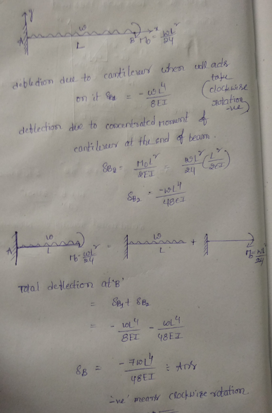
For the cantilever beam with a constant El and loading shown, using the superposition method to...
 For the cantilever beam with a constant El and loading shown, using the superposition method to determine 1) the deflection at B; 2) the slope at B. MWL Mo= 6
1-(25%) Draw shear and moment diagrams for the beam shown in Figure P-1 . Draw a sketch of the deflected shape. The spans are 30-ft long each (total of 90-ft), the concentrated loads are eac...
 1-(25%) Draw shear and moment diagrams for the beam shown in Figure P-1 . Draw a sketch of the deflected shape. The spans are 30-ft long each (total of 90-ft), the concentrated loads are each 120 kips, and placed at the center of left span and the free end. El is constant. Left support is a pin and the other two are roller supports. 120 kips 120 kips Figure P-1
1-(25%) Draw shear and moment diagrams for the beam shown...
1-(25%) Draw shear and moment diagrams for the beam shown in Figure P-1 . Draw a sketch of the deflected shape. The spans are 30-ft long each (total of 90-ft), the concentrated loads are each 120 kips, and placed at the center of left span and the free end. El is constant. Left support is a pin and the other two are roller supports. 120 kips 120 kips Figure P-1
1-(25%) Draw shear and moment diagrams for the beam shown...
Problem 6: The cantilever beam shown below has a constant El-10.000 kN·m2 and is subjected to...
 Problem 6: The cantilever beam shown below has a constant El-10.000 kN·m2 and is subjected to a moment couple at B. Use the double integration method to compute the vertical deflection of the beam at free end A 100 kN-m 2 m
The two-span continuos beam (ABC) shown in the sketch below carries a uniformly distributed load, w,...
 The two-span continuos beam (ABC) shown in the sketch
below carries a uniformly distributed load, w, in the left side
span AB. Assume that EI is constant. Use the method of virtual
work, together with the principle of relative displacements, to
determine the following quantities in terms of E,I,L and
w:
The two-span continuous beam (ABC) shown in the sketch below carries a uniformly distributed load, w, in the left side span AB. Assume that El of the beam is...
The two-span continuos beam (ABC) shown in the sketch
below carries a uniformly distributed load, w, in the left side
span AB. Assume that EI is constant. Use the method of virtual
work, together with the principle of relative displacements, to
determine the following quantities in terms of E,I,L and
w:
The two-span continuous beam (ABC) shown in the sketch below carries a uniformly distributed load, w, in the left side span AB. Assume that El of the beam is...
A cantilever beam supports the loads shown. The cross-sectional dimensions of the shape are also shown....
 A cantilever beam supports the loads shown. The cross-sectional dimensions of the shape are also shown. Assume mm, by - 85 mm, 5 mm, 9 mm. Determine - 0.5 m, P. - 4.0 kN, Pg - 7.5 kN, Pe-2.0 kN, -85 (a) the maximum vertical shear stress. (b) the maximum compression bending stress. (c) the maximum tension bending stress. See the coordinate system for the beam in the problem figure with the origin of the x axis at the feed...
For the beam and loading shown below, identify the individual load cases from the beam tables...
 For the beam and loading shown below, identify the individual load cases from the beam tables that should be applied and sketch the deflected shape to each load case. Then, superimpose the load cases to determine the beam deflection at point H. Assume that El 6 x 10⁴ kN-m2. [Ans.to Check v -10.55 mm 3) 30 kN 7.5 kN/m 1.3 m 3 m
Consider the beam and loading shown. Assume that the flexural rigidity El of the beam is...
 Consider the beam and loading shown. Assume that the flexural rigidity El of the beam is constant А Identify the equation of the elastic curve for the cantilever beam AB
stress analysis ASAP please Question 5 1201 (Energy Method): 5) Determine the equation of the deflection curve of the cantilever beam loaded as shown in Figure. 3. Use as the deflection shape of t...
 stress analysis
ASAP please
Question 5 1201 (Energy Method): 5) Determine the equation of the deflection curve of the cantilever beam loaded as shown in Figure. 3. Use as the deflection shape of the loaded beam Figure 3
Question 5 1201 (Energy Method): 5) Determine the equation of the deflection curve of the cantilever beam loaded as shown in Figure. 3. Use as the deflection shape of the loaded beam Figure 3
stress analysis
ASAP please
Question 5 1201 (Energy Method): 5) Determine the equation of the deflection curve of the cantilever beam loaded as shown in Figure. 3. Use as the deflection shape of the loaded beam Figure 3
Question 5 1201 (Energy Method): 5) Determine the equation of the deflection curve of the cantilever beam loaded as shown in Figure. 3. Use as the deflection shape of the loaded beam Figure 3
A cantilever beam of length L and constant El carries a concentrated load P at a...
 A cantilever beam of length L and constant El carries a concentrated load P at a distance of L/4 from the free end. Use any method that you chose to develop an expression for the deflection of the free end. VEI = ? (The submission does not permit letters so just insert the decimal rather than fraction for the coefficient and show the work on the submitted document) Loading Functie Men - M
Problem 2: Cantilever beam In class we derived the spring constant of a beam of length...
 Problem 2: Cantilever beam In class we derived the spring constant of a beam of length L and constant bending stiffness El clamped at x=0 and subject to a vertical force Fat x= L. Let's study a few different variations of that problem. Let's replace the vertical force F by a counter clockwise bending moement Mo applied at x = L. Recom- pute the equivalent spring constant. Note that in the class we computed spring constant with force and displacement....
 For the cantilever beam with a constant El and loading shown, using the superposition method to determine 1) the deflection at B; 2) the slope at B. MWL Mo= 6
 1-(25%) Draw shear and moment diagrams for the beam shown in Figure P-1 . Draw a sketch of the deflected shape. The spans are 30-ft long each (total of 90-ft), the concentrated loads are each 120 kips, and placed at the center of left span and the free end. El is constant. Left support is a pin and the other two are roller supports. 120 kips 120 kips Figure P-1
1-(25%) Draw shear and moment diagrams for the beam shown...
1-(25%) Draw shear and moment diagrams for the beam shown in Figure P-1 . Draw a sketch of the deflected shape. The spans are 30-ft long each (total of 90-ft), the concentrated loads are each 120 kips, and placed at the center of left span and the free end. El is constant. Left support is a pin and the other two are roller supports. 120 kips 120 kips Figure P-1
1-(25%) Draw shear and moment diagrams for the beam shown...
 Problem 6: The cantilever beam shown below has a constant El-10.000 kN·m2 and is subjected to a moment couple at B. Use the double integration method to compute the vertical deflection of the beam at free end A 100 kN-m 2 m
 The two-span continuos beam (ABC) shown in the sketch
below carries a uniformly distributed load, w, in the left side
span AB. Assume that EI is constant. Use the method of virtual
work, together with the principle of relative displacements, to
determine the following quantities in terms of E,I,L and
w:
The two-span continuous beam (ABC) shown in the sketch below carries a uniformly distributed load, w, in the left side span AB. Assume that El of the beam is...
The two-span continuos beam (ABC) shown in the sketch
below carries a uniformly distributed load, w, in the left side
span AB. Assume that EI is constant. Use the method of virtual
work, together with the principle of relative displacements, to
determine the following quantities in terms of E,I,L and
w:
The two-span continuous beam (ABC) shown in the sketch below carries a uniformly distributed load, w, in the left side span AB. Assume that El of the beam is...
 A cantilever beam supports the loads shown. The cross-sectional dimensions of the shape are also shown. Assume mm, by - 85 mm, 5 mm, 9 mm. Determine - 0.5 m, P. - 4.0 kN, Pg - 7.5 kN, Pe-2.0 kN, -85 (a) the maximum vertical shear stress. (b) the maximum compression bending stress. (c) the maximum tension bending stress. See the coordinate system for the beam in the problem figure with the origin of the x axis at the feed...
 For the beam and loading shown below, identify the individual load cases from the beam tables that should be applied and sketch the deflected shape to each load case. Then, superimpose the load cases to determine the beam deflection at point H. Assume that El 6 x 10⁴ kN-m2. [Ans.to Check v -10.55 mm 3) 30 kN 7.5 kN/m 1.3 m 3 m
 Consider the beam and loading shown. Assume that the flexural rigidity El of the beam is constant А Identify the equation of the elastic curve for the cantilever beam AB
 stress analysis
ASAP please
Question 5 1201 (Energy Method): 5) Determine the equation of the deflection curve of the cantilever beam loaded as shown in Figure. 3. Use as the deflection shape of the loaded beam Figure 3
Question 5 1201 (Energy Method): 5) Determine the equation of the deflection curve of the cantilever beam loaded as shown in Figure. 3. Use as the deflection shape of the loaded beam Figure 3
stress analysis
ASAP please
Question 5 1201 (Energy Method): 5) Determine the equation of the deflection curve of the cantilever beam loaded as shown in Figure. 3. Use as the deflection shape of the loaded beam Figure 3
Question 5 1201 (Energy Method): 5) Determine the equation of the deflection curve of the cantilever beam loaded as shown in Figure. 3. Use as the deflection shape of the loaded beam Figure 3
 A cantilever beam of length L and constant El carries a concentrated load P at a distance of L/4 from the free end. Use any method that you chose to develop an expression for the deflection of the free end. VEI = ? (The submission does not permit letters so just insert the decimal rather than fraction for the coefficient and show the work on the submitted document) Loading Functie Men - M
 Problem 2: Cantilever beam In class we derived the spring constant of a beam of length L and constant bending stiffness El clamped at x=0 and subject to a vertical force Fat x= L. Let's study a few different variations of that problem. Let's replace the vertical force F by a counter clockwise bending moement Mo applied at x = L. Recom- pute the equivalent spring constant. Note that in the class we computed spring constant with force and displacement....
Most questions answered within 3 hours.
-
Where is the error in this code sequence?
String s1 = "Hello";
String s2 = "ello";...
asked 11 months ago -
Financial data for Joel de Paris, Inc., for last year
follow:
Joel de Paris, Inc.
Balance...
asked 11 months ago -
Consider this reaction:
Al2(SO4)3 (aq)+ BaCl3
(aq) Al2Cl6 (aq)- +
3BaSO4(s) . What is the...
asked 11 months ago -
Suppose that Savneet is considering increasing her
recent random sample from 20 car rentals to 40...
asked 11 months ago -
Trucks arrive at an unloading terminal at an average rate of 120
per hour.
Trucks arrive...
asked 11 months ago -
Why are methanol and ethanol completely soluble in water while
octanol is not very little soluble....
asked 11 months ago -
A facilities manager at a university reads in a research report
that the mean amount of...
asked 11 months ago -
When the CuSO4 is rehydrated by adding water to the anhydrous
compound, is this an endothermic...
asked 11 months ago -
A ray of sunlight is passing from diamond into crown glass; the
angle of incidence is...
asked 11 months ago -
A block of mass 0.249 kg is placed on top of a light, vertical
spring of...
asked 11 months ago -
how do the kidneys compensate in the presences of acidosis
a) trigger hyperventilate
b) reserve acid...
asked 11 months ago -
Question 501 pts
The rental rate of capital to the firm increases. Which of the
following...
asked 11 months ago