
Homework Answers
The problem is a straight forward application of the Newton's second law of motion and the Rayleigh's Energy principle.
Consider the following schematics of the geometry and physics of the problem for reference of the derivation.
Note : The solution has been prepared in a hurry, so if there are any mistakes or obscurity in writing, please do let me know in the comment section below.

- Newton's IInd Law :


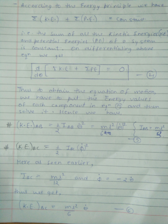
- Energy method :

NOTE: Feel free to ask any further queries in the comment section, down below.
Add Answer to:
Question 4 The slender bars AB and BC of the linkage shown in Figure Q4 have...
Please help with the question! Problem 5 (25pts): Two slender bars AB and BC with lengths...
 Please help with the question!
Problem 5 (25pts): Two slender bars AB and BC with lengths L and 2L are configured as shown. The have mass m and 2m, respectively. When released from rest (dashed line), the bars collapse and move as indicated while point C is constrained to be in constant contact with the wall during the fall. Find the angular velocity of rod BC when it becomes horizontal as shown in the figure. Assume the system is frictionless....
Please help with the question!
Problem 5 (25pts): Two slender bars AB and BC with lengths L and 2L are configured as shown. The have mass m and 2m, respectively. When released from rest (dashed line), the bars collapse and move as indicated while point C is constrained to be in constant contact with the wall during the fall. Find the angular velocity of rod BC when it becomes horizontal as shown in the figure. Assume the system is frictionless....
ke Slender bar of mass m As shown in Figure 1, a uniform slender bar with...
 ke Slender bar of mass m As shown in Figure 1, a uniform slender bar with mass m and length L is supported by a vertical spring at its right end while a mass block 2m suspended from its left end through a spring is supported by another spring. All these three vertical springs have the same stiffness k. If the downward vertical displacement x of the mass block and the clockwise rotation angle 8 of the bar are assumed...
Question 4 A homogeneous slender rod AB of mass m and length L is held in...
 Question 4 A homogeneous slender rod AB of mass m and length L is held in the position shown in Figure Q4. The end A of the rod is free to move along the smooth horizontal surface. The end B of the rod is connected to rod BC of negligible mass. The rod AB is released from rest in the position shown when 0 = 60°. If the acceleration of end B is ā, = -a,j, derive the expressions in...
2. (40 points) A soccer ball tester consists of a 15-kg slender rod AB with a 1.1-kg sim- ulated foot located at A and a torsional spring located at pin B. The torsional spring has a spring const...
 2. (40 points) A soccer ball tester consists of a 15-kg slender rod AB with a 1.1-kg sim- ulated foot located at A and a torsional spring located at pin B. The torsional spring has a spring constant of k 910 N.m/rad and is unstretched when AB is its lowest position. Fig. 2 depicts the simulation. The length of AB is 0.9 m, and you can assume that the foot ban be modcled as a particle, Knowing that the velocity...
2.50 Two slender links, AC and BC, extend from a wall and support a pulley at...
 2.50
Two slender links, AC and BC, extend from a wall and support a pulley at C. A cable, tied at D, passes over the small pulley at C and experience an 80-lb force at its free end E. If the pulley is frictionless and of negligible determine the forces developed in members AC and BC. An inextensible (cannot stretch) cable AC and spring CB are originally horizontal. A 100-N weight is attached to point C, and the system is...
2.50
Two slender links, AC and BC, extend from a wall and support a pulley at C. A cable, tied at D, passes over the small pulley at C and experience an 80-lb force at its free end E. If the pulley is frictionless and of negligible determine the forces developed in members AC and BC. An inextensible (cannot stretch) cable AC and spring CB are originally horizontal. A 100-N weight is attached to point C, and the system is...
QUESTION 2 (10 Marks) The system shown in Figure 2 consists of a couple of bars...
 QUESTION 2 (10 Marks) The system shown in Figure 2 consists of a couple of bars and a wheel. The bar AB rotates at approximately 10 rads in the counter-clockwise direction. Note that the wheel is rolling on a circular surface, however, it is a smooth surface. Using the instantaneous centre of zero velocity method, determine the angular velocities of the wheel and bar BC. (10 marks - C03) I m 1 3 m 2 m 3 m B Figure...
The figure below shows a uniform slender bar supported by cantilevers at A and C. At B a linear spring with stiffness K' is connected to an additional point mass 'm'. Note the physical pr...
 The figure below shows a uniform slender bar supported by cantilevers at A and C. At B a linear spring with stiffness K' is connected to an additional point mass 'm'. Note the physical properties of the bar include cross sectional area A, Young's modulus E, second moment of area I, and, density ρ, and length AB-BC-L. 1. 2. Develop the matrix equation of motion for the FEM system in the model How many natural frequencies are in the system?...
To apply the equations of motion to a system that involves rotation about a fixed axis and to use this information to determine key characteristics. The slender rod AB shown has a mass of m=57.0 kg an...
 To apply the equations of motion to a system that involves
rotation about a fixed axis and to use this information to
determine key characteristics.
The slender rod AB shown has a mass of m=57.0 kg and is being
supported by a rope and pulley system stationed at C. Starting from
rest (in the position shown), the rope and pulley system tug on the
rod causing it to rotate about A. The torque applied to the pulley
is T=2.25 kN⋅m...
To apply the equations of motion to a system that involves
rotation about a fixed axis and to use this information to
determine key characteristics.
The slender rod AB shown has a mass of m=57.0 kg and is being
supported by a rope and pulley system stationed at C. Starting from
rest (in the position shown), the rope and pulley system tug on the
rod causing it to rotate about A. The torque applied to the pulley
is T=2.25 kN⋅m...
Prob. 3 The system shown has 4 particles at the corners of a square of side connected by only tiwo slender bars that lie along the two diagonals of the square. Each particle and each bar has a ma...
 Prob. 3 The system shown has 4 particles at the corners of a square of side connected by only tiwo slender bars that lie along the two diagonals of the square. Each particle and each bar has a mass m = 2 kg. Determine the mass, locate the center of mass G of the system, and determine its moment of inertia and radius of gyration about G. L = 600 mm. The particles are
Prob. 3 The system shown has...
Prob. 3 The system shown has 4 particles at the corners of a square of side connected by only tiwo slender bars that lie along the two diagonals of the square. Each particle and each bar has a mass m = 2 kg. Determine the mass, locate the center of mass G of the system, and determine its moment of inertia and radius of gyration about G. L = 600 mm. The particles are
Prob. 3 The system shown has...
The mass of the uniform slender steel rod, shown in Figure 2, is 3 kg. The...
 The mass of the uniform slender steel rod, shown in Figure 2, is 3 kg. The system is set in motion with small oscillations about the horizontal equilibrium position shown. (i) Determine the position x for the slider such that the system period is 1 s. (ii) When the pivot is replaced by a built-in support that restricts any rotation at O and the spring is moved to the right-hand end with the 1.2 kg mass removed, calculate the frequency...
 Please help with the question!
Problem 5 (25pts): Two slender bars AB and BC with lengths L and 2L are configured as shown. The have mass m and 2m, respectively. When released from rest (dashed line), the bars collapse and move as indicated while point C is constrained to be in constant contact with the wall during the fall. Find the angular velocity of rod BC when it becomes horizontal as shown in the figure. Assume the system is frictionless....
Please help with the question!
Problem 5 (25pts): Two slender bars AB and BC with lengths L and 2L are configured as shown. The have mass m and 2m, respectively. When released from rest (dashed line), the bars collapse and move as indicated while point C is constrained to be in constant contact with the wall during the fall. Find the angular velocity of rod BC when it becomes horizontal as shown in the figure. Assume the system is frictionless....
 ke Slender bar of mass m As shown in Figure 1, a uniform slender bar with mass m and length L is supported by a vertical spring at its right end while a mass block 2m suspended from its left end through a spring is supported by another spring. All these three vertical springs have the same stiffness k. If the downward vertical displacement x of the mass block and the clockwise rotation angle 8 of the bar are assumed...
 Question 4 A homogeneous slender rod AB of mass m and length L is held in the position shown in Figure Q4. The end A of the rod is free to move along the smooth horizontal surface. The end B of the rod is connected to rod BC of negligible mass. The rod AB is released from rest in the position shown when 0 = 60°. If the acceleration of end B is ā, = -a,j, derive the expressions in...
 2. (40 points) A soccer ball tester consists of a 15-kg slender rod AB with a 1.1-kg sim- ulated foot located at A and a torsional spring located at pin B. The torsional spring has a spring constant of k 910 N.m/rad and is unstretched when AB is its lowest position. Fig. 2 depicts the simulation. The length of AB is 0.9 m, and you can assume that the foot ban be modcled as a particle, Knowing that the velocity...
 2.50
Two slender links, AC and BC, extend from a wall and support a pulley at C. A cable, tied at D, passes over the small pulley at C and experience an 80-lb force at its free end E. If the pulley is frictionless and of negligible determine the forces developed in members AC and BC. An inextensible (cannot stretch) cable AC and spring CB are originally horizontal. A 100-N weight is attached to point C, and the system is...
2.50
Two slender links, AC and BC, extend from a wall and support a pulley at C. A cable, tied at D, passes over the small pulley at C and experience an 80-lb force at its free end E. If the pulley is frictionless and of negligible determine the forces developed in members AC and BC. An inextensible (cannot stretch) cable AC and spring CB are originally horizontal. A 100-N weight is attached to point C, and the system is...
 QUESTION 2 (10 Marks) The system shown in Figure 2 consists of a couple of bars and a wheel. The bar AB rotates at approximately 10 rads in the counter-clockwise direction. Note that the wheel is rolling on a circular surface, however, it is a smooth surface. Using the instantaneous centre of zero velocity method, determine the angular velocities of the wheel and bar BC. (10 marks - C03) I m 1 3 m 2 m 3 m B Figure...
 The figure below shows a uniform slender bar supported by cantilevers at A and C. At B a linear spring with stiffness K' is connected to an additional point mass 'm'. Note the physical properties of the bar include cross sectional area A, Young's modulus E, second moment of area I, and, density ρ, and length AB-BC-L. 1. 2. Develop the matrix equation of motion for the FEM system in the model How many natural frequencies are in the system?...
 To apply the equations of motion to a system that involves
rotation about a fixed axis and to use this information to
determine key characteristics.
The slender rod AB shown has a mass of m=57.0 kg and is being
supported by a rope and pulley system stationed at C. Starting from
rest (in the position shown), the rope and pulley system tug on the
rod causing it to rotate about A. The torque applied to the pulley
is T=2.25 kN⋅m...
To apply the equations of motion to a system that involves
rotation about a fixed axis and to use this information to
determine key characteristics.
The slender rod AB shown has a mass of m=57.0 kg and is being
supported by a rope and pulley system stationed at C. Starting from
rest (in the position shown), the rope and pulley system tug on the
rod causing it to rotate about A. The torque applied to the pulley
is T=2.25 kN⋅m...
 Prob. 3 The system shown has 4 particles at the corners of a square of side connected by only tiwo slender bars that lie along the two diagonals of the square. Each particle and each bar has a mass m = 2 kg. Determine the mass, locate the center of mass G of the system, and determine its moment of inertia and radius of gyration about G. L = 600 mm. The particles are
Prob. 3 The system shown has...
Prob. 3 The system shown has 4 particles at the corners of a square of side connected by only tiwo slender bars that lie along the two diagonals of the square. Each particle and each bar has a mass m = 2 kg. Determine the mass, locate the center of mass G of the system, and determine its moment of inertia and radius of gyration about G. L = 600 mm. The particles are
Prob. 3 The system shown has...
 The mass of the uniform slender steel rod, shown in Figure 2, is 3 kg. The system is set in motion with small oscillations about the horizontal equilibrium position shown. (i) Determine the position x for the slider such that the system period is 1 s. (ii) When the pivot is replaced by a built-in support that restricts any rotation at O and the spring is moved to the right-hand end with the 1.2 kg mass removed, calculate the frequency...
Most questions answered within 3 hours.
-
Where is the error in this code sequence?
String s1 = "Hello";
String s2 = "ello";...
asked 11 months ago -
Financial data for Joel de Paris, Inc., for last year
follow:
Joel de Paris, Inc.
Balance...
asked 11 months ago -
Consider this reaction:
Al2(SO4)3 (aq)+ BaCl3
(aq) Al2Cl6 (aq)- +
3BaSO4(s) . What is the...
asked 11 months ago -
Suppose that Savneet is considering increasing her
recent random sample from 20 car rentals to 40...
asked 11 months ago -
Trucks arrive at an unloading terminal at an average rate of 120
per hour.
Trucks arrive...
asked 11 months ago -
Why are methanol and ethanol completely soluble in water while
octanol is not very little soluble....
asked 11 months ago -
A facilities manager at a university reads in a research report
that the mean amount of...
asked 11 months ago -
When the CuSO4 is rehydrated by adding water to the anhydrous
compound, is this an endothermic...
asked 11 months ago -
A ray of sunlight is passing from diamond into crown glass; the
angle of incidence is...
asked 11 months ago -
A block of mass 0.249 kg is placed on top of a light, vertical
spring of...
asked 11 months ago -
how do the kidneys compensate in the presences of acidosis
a) trigger hyperventilate
b) reserve acid...
asked 11 months ago -
Question 501 pts
The rental rate of capital to the firm increases. Which of the
following...
asked 11 months ago