
Homework Answers


Add Answer to:
ke Slender bar of mass m As shown in Figure 1, a uniform slender bar with...
The spring is uncompressed when the uniform slender bar is in the vertical position shown. Determine...
 The spring is uncompressed when the uniform slender bar is in the vertical position shown. Determine the initial angular acceleration a of the bar when it is released from rest in a position where the bar has been rotated clockwise 33° from the position shown. Neglect any sag of the spring, whose mass is negligible. The angular acceleration is positive if counterclockwise and negative if clockwise. The mass m of the bar is 18 kg, the length / is 305...
The figure below shows a uniform slender bar supported by cantilevers at A and C. At B a linear spring with stiffness K' is connected to an additional point mass 'm'. Note the physical pr...
 The figure below shows a uniform slender bar supported by cantilevers at A and C. At B a linear spring with stiffness K' is connected to an additional point mass 'm'. Note the physical properties of the bar include cross sectional area A, Young's modulus E, second moment of area I, and, density ρ, and length AB-BC-L. 1. 2. Develop the matrix equation of motion for the FEM system in the model How many natural frequencies are in the system?...
5.22. Verify that the natural modes in Example 5.2 are orthogonal with respect to both the mass m...
 Solve problem 5.22 by using example 5.2
5.22. Verify that the natural modes in Example 5.2 are orthogonal with respect to both the mass matrix and the stiffness matrix. 5.2. A rigid bar of mass per unit length m carries a point mass M at its right end. The bar is supported by two springs, as shown in Fig. 5.21. Derive the differential equations for the translation and rotation of the mass center. Assume small motions. A F(t) k2 4...
Solve problem 5.22 by using example 5.2
5.22. Verify that the natural modes in Example 5.2 are orthogonal with respect to both the mass matrix and the stiffness matrix. 5.2. A rigid bar of mass per unit length m carries a point mass M at its right end. The bar is supported by two springs, as shown in Fig. 5.21. Derive the differential equations for the translation and rotation of the mass center. Assume small motions. A F(t) k2 4...
44. The system shown in Fig. P7 consists of a slider block of mass m2 and a uniform slender rod of mass m3, length 13, and mass moment of inertia about its center of mass J The slider block is connec...
 44. The system shown in Fig. P7 consists of a slider block of mass m2 and a uniform slender rod of mass m3, length 13, and mass moment of inertia about its center of mass J The slider block is connected to the ground by a spring that has a stiffness coefficient k. The slider block is subjected to the force F(t), while the rod is subjected to the moment M. Obtain the differential equations of motion of this two-degree-of-freedom...
sos Problem 3: [2, 03-15] A rigid and uniform bar undergoing rota- tional motions in the...
 sos
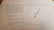
Problem 3: [2, 03-15] A rigid and uniform bar undergoing rota- tional motions in the vertical plane is re- strained by a torsional spring of stiffness k at the pivot point O, as shown in the figure. The bar has mass m and a length& and the torsional spring is unstretched in the upright position a) Find the equations of motion, lin- ke earized about 6 0: b) Determine what ke should be so that small oscillations about the...
sos
Problem 3: [2, 03-15] A rigid and uniform bar undergoing rota- tional motions in the vertical plane is re- strained by a torsional spring of stiffness k at the pivot point O, as shown in the figure. The bar has mass m and a length& and the torsional spring is unstretched in the upright position a) Find the equations of motion, lin- ke earized about 6 0: b) Determine what ke should be so that small oscillations about the...
Figure P3.34 A slender rod 1.4 m long and of mass 20 kg is attached to...
 Figure P3.34 A slender rod 1.4 m long and of mass 20 kg is attached to a wheel of mass 3 kg and radius 0.05 m, as shown in Figure P3.34. A horizontal force f is applied to the wheel axle. Derive the equations of motion in terms of angular displacement θ of the rod and displacement Xp of the wheel center Assume the wheel does not slip Linearize the resulting equations Extra credit (2 points each) a. If force...
Problem 3.35 (6 points) Figure P3.34 A slender rod 1.4 m long and of mass 20 kg is attached to a ...
 part a and b only first paragraph already done (theta)
Problem 3.35 (6 points) Figure P3.34 A slender rod 1.4 m long and of mass 20 kg is attached to a wheel of mass 3 kgP and radius 0.05 m, as shown in Figure P3.34. A horizontal force f is applied to the wheel axle. Derive the equations of motion in terms of angular displacement θ of the rod and displacement-V,ofthe wheel center Assume the wheel does not slip. Linearize...
part a and b only first paragraph already done (theta)
Problem 3.35 (6 points) Figure P3.34 A slender rod 1.4 m long and of mass 20 kg is attached to a wheel of mass 3 kgP and radius 0.05 m, as shown in Figure P3.34. A horizontal force f is applied to the wheel axle. Derive the equations of motion in terms of angular displacement θ of the rod and displacement-V,ofthe wheel center Assume the wheel does not slip. Linearize...
Question 4 The slender bars AB and BC of the linkage shown in Figure Q4 have...
 Question 4 The slender bars AB and BC of the linkage shown in Figure Q4 have mass m and length I, and the collar C has mass m. A torsional spring at A which has a stiffiness of k, exerts a torque on the bar AB. Knowing that when o-0, the system is in equilibrium and the torsional spring which is attached to the slender bar AB is not twisted. If the system is perturbed a bit from equilibrium and...
A mass block of mass m1 is attached to the rigid and weightless bar ABC whose...
 A mass block of mass m1 is attached to the rigid and weightless bar ABC whose other end is pin-connected to the wall The bar is supported by a spring of spring constant of k3 at its midpoint B. AB BC-a-1m. Another block of mass m2 is connected to the first block by a spring of spring constant k1 and is connected to the fixed ground by a spring of spring constant k2. The size of both blocks are ignored....
The mass of the uniform slender steel rod, shown in Figure 2, is 3 kg. The...
 The mass of the uniform slender steel rod, shown in Figure 2, is 3 kg. The system is set in motion with small oscillations about the horizontal equilibrium position shown. (i) Determine the position x for the slider such that the system period is 1 s. (ii) When the pivot is replaced by a built-in support that restricts any rotation at O and the spring is moved to the right-hand end with the 1.2 kg mass removed, calculate the frequency...
 The spring is uncompressed when the uniform slender bar is in the vertical position shown. Determine the initial angular acceleration a of the bar when it is released from rest in a position where the bar has been rotated clockwise 33° from the position shown. Neglect any sag of the spring, whose mass is negligible. The angular acceleration is positive if counterclockwise and negative if clockwise. The mass m of the bar is 18 kg, the length / is 305...
 The figure below shows a uniform slender bar supported by cantilevers at A and C. At B a linear spring with stiffness K' is connected to an additional point mass 'm'. Note the physical properties of the bar include cross sectional area A, Young's modulus E, second moment of area I, and, density ρ, and length AB-BC-L. 1. 2. Develop the matrix equation of motion for the FEM system in the model How many natural frequencies are in the system?...
 Solve problem 5.22 by using example 5.2
5.22. Verify that the natural modes in Example 5.2 are orthogonal with respect to both the mass matrix and the stiffness matrix. 5.2. A rigid bar of mass per unit length m carries a point mass M at its right end. The bar is supported by two springs, as shown in Fig. 5.21. Derive the differential equations for the translation and rotation of the mass center. Assume small motions. A F(t) k2 4...
Solve problem 5.22 by using example 5.2
5.22. Verify that the natural modes in Example 5.2 are orthogonal with respect to both the mass matrix and the stiffness matrix. 5.2. A rigid bar of mass per unit length m carries a point mass M at its right end. The bar is supported by two springs, as shown in Fig. 5.21. Derive the differential equations for the translation and rotation of the mass center. Assume small motions. A F(t) k2 4...
 44. The system shown in Fig. P7 consists of a slider block of mass m2 and a uniform slender rod of mass m3, length 13, and mass moment of inertia about its center of mass J The slider block is connected to the ground by a spring that has a stiffness coefficient k. The slider block is subjected to the force F(t), while the rod is subjected to the moment M. Obtain the differential equations of motion of this two-degree-of-freedom...
 sos
Problem 3: [2, 03-15] A rigid and uniform bar undergoing rota- tional motions in the vertical plane is re- strained by a torsional spring of stiffness k at the pivot point O, as shown in the figure. The bar has mass m and a length& and the torsional spring is unstretched in the upright position a) Find the equations of motion, lin- ke earized about 6 0: b) Determine what ke should be so that small oscillations about the...
sos
Problem 3: [2, 03-15] A rigid and uniform bar undergoing rota- tional motions in the vertical plane is re- strained by a torsional spring of stiffness k at the pivot point O, as shown in the figure. The bar has mass m and a length& and the torsional spring is unstretched in the upright position a) Find the equations of motion, lin- ke earized about 6 0: b) Determine what ke should be so that small oscillations about the...
 Figure P3.34 A slender rod 1.4 m long and of mass 20 kg is attached to a wheel of mass 3 kg and radius 0.05 m, as shown in Figure P3.34. A horizontal force f is applied to the wheel axle. Derive the equations of motion in terms of angular displacement θ of the rod and displacement Xp of the wheel center Assume the wheel does not slip Linearize the resulting equations Extra credit (2 points each) a. If force...
 part a and b only first paragraph already done (theta)
Problem 3.35 (6 points) Figure P3.34 A slender rod 1.4 m long and of mass 20 kg is attached to a wheel of mass 3 kgP and radius 0.05 m, as shown in Figure P3.34. A horizontal force f is applied to the wheel axle. Derive the equations of motion in terms of angular displacement θ of the rod and displacement-V,ofthe wheel center Assume the wheel does not slip. Linearize...
part a and b only first paragraph already done (theta)
Problem 3.35 (6 points) Figure P3.34 A slender rod 1.4 m long and of mass 20 kg is attached to a wheel of mass 3 kgP and radius 0.05 m, as shown in Figure P3.34. A horizontal force f is applied to the wheel axle. Derive the equations of motion in terms of angular displacement θ of the rod and displacement-V,ofthe wheel center Assume the wheel does not slip. Linearize...
 Question 4 The slender bars AB and BC of the linkage shown in Figure Q4 have mass m and length I, and the collar C has mass m. A torsional spring at A which has a stiffiness of k, exerts a torque on the bar AB. Knowing that when o-0, the system is in equilibrium and the torsional spring which is attached to the slender bar AB is not twisted. If the system is perturbed a bit from equilibrium and...
 A mass block of mass m1 is attached to the rigid and weightless bar ABC whose other end is pin-connected to the wall The bar is supported by a spring of spring constant of k3 at its midpoint B. AB BC-a-1m. Another block of mass m2 is connected to the first block by a spring of spring constant k1 and is connected to the fixed ground by a spring of spring constant k2. The size of both blocks are ignored....
 The mass of the uniform slender steel rod, shown in Figure 2, is 3 kg. The system is set in motion with small oscillations about the horizontal equilibrium position shown. (i) Determine the position x for the slider such that the system period is 1 s. (ii) When the pivot is replaced by a built-in support that restricts any rotation at O and the spring is moved to the right-hand end with the 1.2 kg mass removed, calculate the frequency...
Most questions answered within 3 hours.
-
Where is the error in this code sequence?
String s1 = "Hello";
String s2 = "ello";...
asked 11 months ago -
Financial data for Joel de Paris, Inc., for last year
follow:
Joel de Paris, Inc.
Balance...
asked 11 months ago -
Consider this reaction:
Al2(SO4)3 (aq)+ BaCl3
(aq) Al2Cl6 (aq)- +
3BaSO4(s) . What is the...
asked 11 months ago -
Suppose that Savneet is considering increasing her
recent random sample from 20 car rentals to 40...
asked 11 months ago -
Trucks arrive at an unloading terminal at an average rate of 120
per hour.
Trucks arrive...
asked 11 months ago -
Why are methanol and ethanol completely soluble in water while
octanol is not very little soluble....
asked 11 months ago -
A facilities manager at a university reads in a research report
that the mean amount of...
asked 11 months ago -
When the CuSO4 is rehydrated by adding water to the anhydrous
compound, is this an endothermic...
asked 11 months ago -
A ray of sunlight is passing from diamond into crown glass; the
angle of incidence is...
asked 11 months ago -
A block of mass 0.249 kg is placed on top of a light, vertical
spring of...
asked 11 months ago -
how do the kidneys compensate in the presences of acidosis
a) trigger hyperventilate
b) reserve acid...
asked 11 months ago -
Question 501 pts
The rental rate of capital to the firm increases. Which of the
following...
asked 11 months ago