
Homework Answers
Add Answer to:
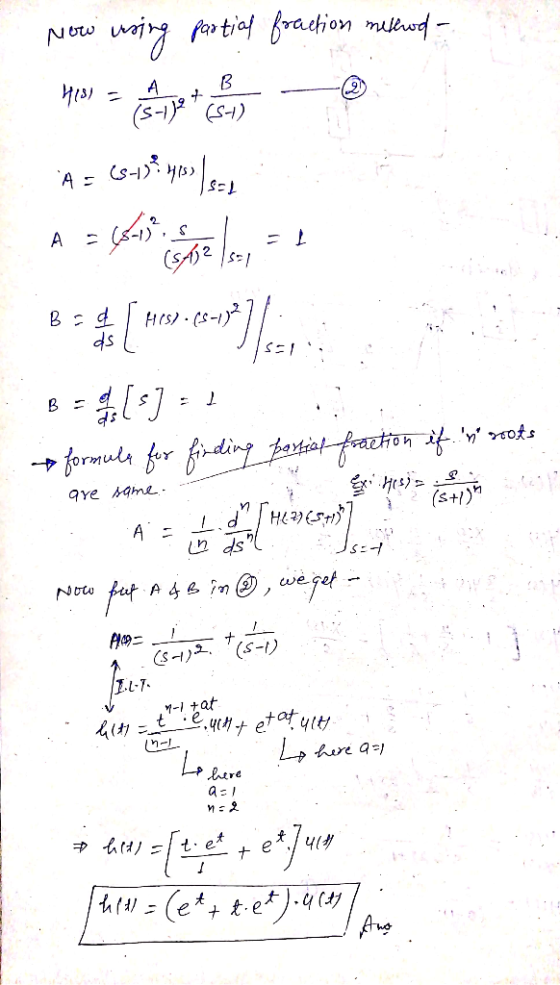
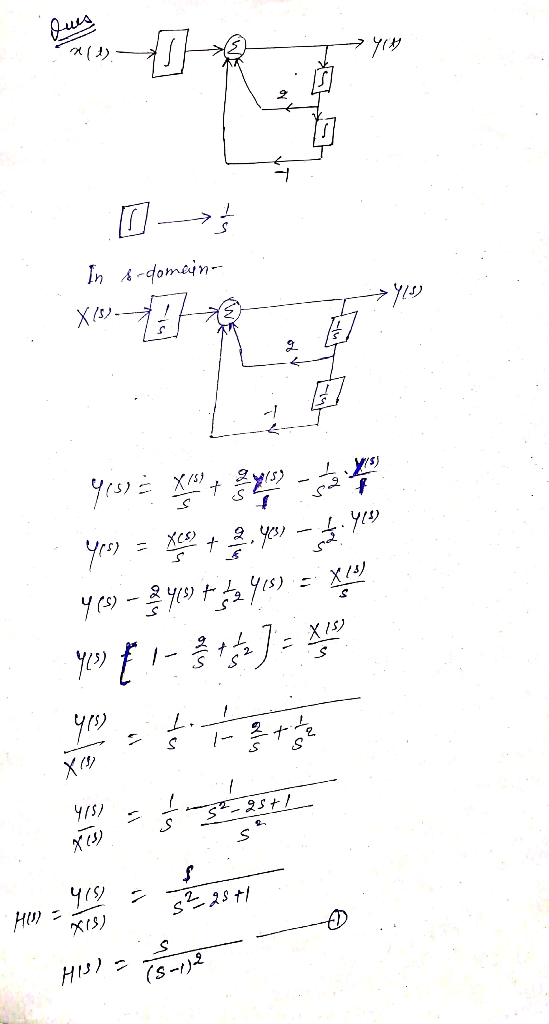
VA1.For the block diagram shown on the left, use frequency domain methods to obtain the impulse...
Use frequency domain methods to obtain the unit sample response of the system: You should use d...
Use frequency domain methods to obtain the unit sample response of the system: You should use discrete time Fourier transforms for this We were unable to transcribe this imagey[n] ㅡ 출yIn _ 1] + _ 2] = 2.rln _ 1]-.rln-2 y[n] ㅡ 출yIn _ 1] + _ 2] = 2.rln _ 1]-.rln-2
03. (a) Consider the block diagram shown in Figure 3.1, and assume G(s)= 3. G,(s) and...
 03. (a) Consider the block diagram shown in Figure 3.1, and assume G(s)= 3. G,(s) and G,(s) 5+2 Y(s) R(S) G,() Gy(s) G;(s) Figure 3.1 3 (0) Y(s) Derive the system transfer function H(s)= of the system. Plot the R(s) poles and zeros of H(s) in the complex s-plane. State whether the system is stable or not stable, and why. [10 marks) (11) Obtain the impulse response of the system, that is ylt) for r(t)= 8(t). Evaluate the final value...
Problem 4. Linear Time-Invariant System.s A linear system has the block diagram y(t) z(t) →| Delay...
 Problem 4. Linear Time-Invariant System.s A linear system has the block diagram y(t) z(t) →| Delay by 1 dt *h(t) where g(t) sinc(t Since this is a linear time invariant system, we can represent it as a convolution with a single impulse response h(t) a) Find the impulse response h(t). You don't need to explicitly differentiate. b) Find the frequency response H(j for this system.
yce) Figure 1: Time-domain block diagram, with input u(t) and output y(t). For the block diagram...
 yce) Figure 1: Time-domain block diagram, with input u(t) and output y(t). For the block diagram shown in Figure find the system transfer function Y (s)/U(s).
Problem 2: /25 For the circuit shown below, use frequency-domain circuit analysis techniques to determine (a)...
 Problem 2: /25 For the circuit shown below, use frequency-domain circuit analysis techniques to determine (a) the voltage transfer function H(o) of the circuit; (b) the magnitude response H(o) of the circuit; and (c) the phase response (0) of the circuit. (d) Based on the results of parts (a) - (c), identify the type of filter circuit shown. L 10000 + + R Vout(t)
Q1) Consider an LTI system with frequency response (u) given by (a) Find the impulse response h(0) for this system. [Hint: In case of polynomial over pohnomial frequency domain representation, we...
 Q1) Consider an LTI system with frequency response (u) given by (a) Find the impulse response h(0) for this system. [Hint: In case of polynomial over pohnomial frequency domain representation, we analyce the denominator and use partial fraction expansion to write H() in the form Then we notice that each of these fraction terms is the Fourier of an exponentiol multiplied by a unit step as per the Table J (b) What is the output y(t) from the system if...
PROBLEMS B-2-1. Simplify the block diagram shown in Figure 2-29 and obtain the closed-loop transfer function...
 PROBLEMS B-2-1. Simplify the block diagram shown in Figure 2-29 and obtain the closed-loop transfer function C(s)/RS). B-2-2. Simplify the block diagram shown in Figure 2-30 and obtain the closed-loop transfer function C(s)/R(s). B-2-3. Simplify the block diagram shown in Figure 2-31 and obtain the closed-loop transfer function C(s)/R(S). G1 R(S) CS) Figure 2-29 Block diagram of a system. Figure 2-30 Block diagram of a system. Figure 2-31 Block diagram of a system.
Problem 1: /25 For the circuit shown below, use frequency-domain circuit analysis techniques to determine (a)...
 Problem 1: /25 For the circuit shown below, use frequency-domain circuit analysis techniques to determine (a) the voltage transfer function Ho) of the circuit; (b) the magnitude response H(o) of the circuit; and (c) the phase response (0) of the circuit. (d) Based on the results of parts (a) - (c), identify the type of filter circuit shown. R + Vin(t) llll L Vout(t)
Problem 3: /25 For the circuit shown below, use frequency-domain circuit analysis techniques to determine (a)...
 Problem 3: /25 For the circuit shown below, use frequency-domain circuit analysis techniques to determine (a) the voltage transfer function Ho) of the circuit; (b) the magnitude response H(@) of the circuit; and (c) the phase response (0) of the circuit. (d) Based on the results of parts (a) - (c), identify the type of filter circuit shown. с R + + Vin(t) 0000 L Vout(t)
3. (20 points) A system has an impulse response given by h (t) sin (2t) rt...
 3. (20 points) A system has an impulse response given by h (t) sin (2t) rt (a) Find the frequency response function of this system H (w). (b) Find the frequency domain output Y (w) if the input to the system is z (t) cos (3t).
 03. (a) Consider the block diagram shown in Figure 3.1, and assume G(s)= 3. G,(s) and G,(s) 5+2 Y(s) R(S) G,() Gy(s) G;(s) Figure 3.1 3 (0) Y(s) Derive the system transfer function H(s)= of the system. Plot the R(s) poles and zeros of H(s) in the complex s-plane. State whether the system is stable or not stable, and why. [10 marks) (11) Obtain the impulse response of the system, that is ylt) for r(t)= 8(t). Evaluate the final value...
 Problem 4. Linear Time-Invariant System.s A linear system has the block diagram y(t) z(t) →| Delay by 1 dt *h(t) where g(t) sinc(t Since this is a linear time invariant system, we can represent it as a convolution with a single impulse response h(t) a) Find the impulse response h(t). You don't need to explicitly differentiate. b) Find the frequency response H(j for this system.
 yce) Figure 1: Time-domain block diagram, with input u(t) and output y(t). For the block diagram shown in Figure find the system transfer function Y (s)/U(s).
 Problem 2: /25 For the circuit shown below, use frequency-domain circuit analysis techniques to determine (a) the voltage transfer function H(o) of the circuit; (b) the magnitude response H(o) of the circuit; and (c) the phase response (0) of the circuit. (d) Based on the results of parts (a) - (c), identify the type of filter circuit shown. L 10000 + + R Vout(t)
 Q1) Consider an LTI system with frequency response (u) given by (a) Find the impulse response h(0) for this system. [Hint: In case of polynomial over pohnomial frequency domain representation, we analyce the denominator and use partial fraction expansion to write H() in the form Then we notice that each of these fraction terms is the Fourier of an exponentiol multiplied by a unit step as per the Table J (b) What is the output y(t) from the system if...
 PROBLEMS B-2-1. Simplify the block diagram shown in Figure 2-29 and obtain the closed-loop transfer function C(s)/RS). B-2-2. Simplify the block diagram shown in Figure 2-30 and obtain the closed-loop transfer function C(s)/R(s). B-2-3. Simplify the block diagram shown in Figure 2-31 and obtain the closed-loop transfer function C(s)/R(S). G1 R(S) CS) Figure 2-29 Block diagram of a system. Figure 2-30 Block diagram of a system. Figure 2-31 Block diagram of a system.
 Problem 1: /25 For the circuit shown below, use frequency-domain circuit analysis techniques to determine (a) the voltage transfer function Ho) of the circuit; (b) the magnitude response H(o) of the circuit; and (c) the phase response (0) of the circuit. (d) Based on the results of parts (a) - (c), identify the type of filter circuit shown. R + Vin(t) llll L Vout(t)
 Problem 3: /25 For the circuit shown below, use frequency-domain circuit analysis techniques to determine (a) the voltage transfer function Ho) of the circuit; (b) the magnitude response H(@) of the circuit; and (c) the phase response (0) of the circuit. (d) Based on the results of parts (a) - (c), identify the type of filter circuit shown. с R + + Vin(t) 0000 L Vout(t)
 3. (20 points) A system has an impulse response given by h (t) sin (2t) rt (a) Find the frequency response function of this system H (w). (b) Find the frequency domain output Y (w) if the input to the system is z (t) cos (3t).
Most questions answered within 3 hours.
-
Where is the error in this code sequence?
String s1 = "Hello";
String s2 = "ello";...
asked 11 months ago -
Financial data for Joel de Paris, Inc., for last year
follow:
Joel de Paris, Inc.
Balance...
asked 11 months ago -
Consider this reaction:
Al2(SO4)3 (aq)+ BaCl3
(aq) Al2Cl6 (aq)- +
3BaSO4(s) . What is the...
asked 11 months ago -
Suppose that Savneet is considering increasing her
recent random sample from 20 car rentals to 40...
asked 11 months ago -
Trucks arrive at an unloading terminal at an average rate of 120
per hour.
Trucks arrive...
asked 11 months ago -
Why are methanol and ethanol completely soluble in water while
octanol is not very little soluble....
asked 11 months ago -
A facilities manager at a university reads in a research report
that the mean amount of...
asked 11 months ago -
When the CuSO4 is rehydrated by adding water to the anhydrous
compound, is this an endothermic...
asked 11 months ago -
A ray of sunlight is passing from diamond into crown glass; the
angle of incidence is...
asked 11 months ago -
A block of mass 0.249 kg is placed on top of a light, vertical
spring of...
asked 11 months ago -
how do the kidneys compensate in the presences of acidosis
a) trigger hyperventilate
b) reserve acid...
asked 11 months ago -
Question 501 pts
The rental rate of capital to the firm increases. Which of the
following...
asked 11 months ago