
Homework Answers
Add Answer to:
IV. Design of a four bar mechanism (ABCD) according to the following 3 positons (Fig.5), find...
Please Solve and Give Detail. Thank you. For a four-bar mechanism, the link lengths in inches...
 Please Solve and Give Detail. Thank you.
For a four-bar mechanism, the link lengths in inches and the value of the angle 02 are as follows: Link 1-5, Link 2-3, Link 3-8, Link 4-9, θ. = 45 degrees. Link l is the ground and link 2 is the driving link. (a) Is this a crank-rocker, double rocker, double crank or triple rocker mechanism? Justify your answer. [5 points] (b) Find the angles 0.04 and transmission angle when θ2 45 degrees...
Please Solve and Give Detail. Thank you.
For a four-bar mechanism, the link lengths in inches and the value of the angle 02 are as follows: Link 1-5, Link 2-3, Link 3-8, Link 4-9, θ. = 45 degrees. Link l is the ground and link 2 is the driving link. (a) Is this a crank-rocker, double rocker, double crank or triple rocker mechanism? Justify your answer. [5 points] (b) Find the angles 0.04 and transmission angle when θ2 45 degrees...
For the four bar linkage mechanism shown in the figure, determine all angles,the maximum and minimum...
 For the four bar linkage mechanism shown in the
figure, determine all angles,the maximum and minimum transmission
angles,the sweep angle, and the angular velocities of elements AB
and O4B, if element O2A rotates at 3 rad/a CCW
Problem 1. For the four-bar linkage mechanism shown in the figure, determine all angles, the maximum and minimum transmission angles, the sweep angle, and the angular velocities of elements AB and O.B, if element O, A rotates at 3 rad/s CCW. 10" 03...
For the four bar linkage mechanism shown in the
figure, determine all angles,the maximum and minimum transmission
angles,the sweep angle, and the angular velocities of elements AB
and O4B, if element O2A rotates at 3 rad/a CCW
Problem 1. For the four-bar linkage mechanism shown in the figure, determine all angles, the maximum and minimum transmission angles, the sweep angle, and the angular velocities of elements AB and O.B, if element O, A rotates at 3 rad/s CCW. 10" 03...
#1. Design a crank rocker mechanism (four bar linkage) where the rocker length is between 3...
 #1. Design a crank rocker mechanism (four bar linkage) where the rocker length is between 3 inch and 3.5 inch with a swing angle of about 45 degree. Also the time ratio (Q) of the linkage is required to be between 1.5 and 1.75 (20 pts). Clearly show the lengths of the crank, coupler and fixed frame of your design (10 pts). Locate a coupler point about o.S inch above the mid-point of your coupler (5 pts). Draw the linkage...
Q-8 Design a quick-return crank-and-rocker four-bar mechanism to provide a transmission ratio of TR = α/β...
Q-8 Design a quick-return crank-and-rocker four-bar mechanism to provide a transmission ratio of TR = α/β = 1/1.25 and output rocker motion of 60 degree (α + β = 360o).
The pin-connected structure shown in Fig. 5 consists of a rigid bar ABCD and two 1,500-mm-long...
 The pin-connected structure shown in Fig. 5 consists of a rigid bar ABCD and two 1,500-mm-long bars. Bar (1) is steel [E=200 GPa] with a cross-sectional area of A1 = 510 mm2. Bar (2) is an aluminium alloy [E-70 GPa] with a cross-sectional area of A2 1,300 mm2. All bars are unstressed before the load P is applied. If a concentrated load of P 200 kN acts on the structure at D determine: (a) the normal stresses in both bars...
The mechanism consists of two sliders connected by a rigid bar, on two surfaces. R3 and...
 The mechanism consists of two sliders connected by a rigid bar,
on two surfaces. R3 and angle (0<Ф<π) between the surface is
constant. R3 = 10√3, Ф = 120°, r1 =10, r2 = 10 and ω3 = 5.
Find the velocities of both sliders using the following
methods:
a) Analytical
b) Graphical
B2
B2
The mechanism consists of two sliders connected by a rigid bar,
on two surfaces. R3 and angle (0<Ф<π) between the surface is
constant. R3 = 10√3, Ф = 120°, r1 =10, r2 = 10 and ω3 = 5.
Find the velocities of both sliders using the following
methods:
a) Analytical
b) Graphical
B2
B2
Problem 1. For the four-bar linkage mechanism shown in the figure, determine all angles, the maximum...
 Problem 1. For the four-bar linkage mechanism shown in the figure, determine all angles, the maximum and minimum transmission angles, the sweep angle, and the angular velocities of elements AB and 04B, if element O2A rotates at 3 rad/s CCW. B 10" B 03 26" А 13 3 A 12 / 2 4 74 ф 04 10" 8" 8" 02 AC 02 6" 24" 404
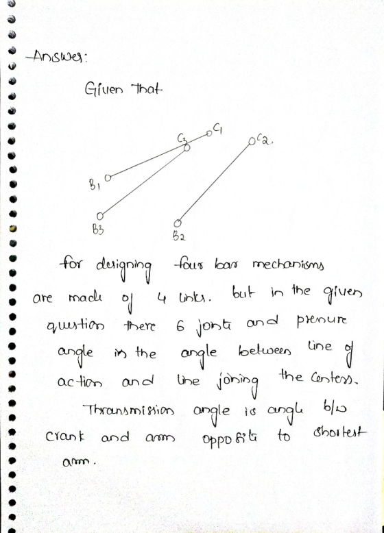
In the drawing, AB is 1.25 cm. Use A and B as circle points, and design a four-bar linkage to move its coupler through the three positions shown. Use Grashofs equation to investigate the motion. в...
 In the drawing, AB is 1.25 cm. Use A and B as circle points, and design a four-bar linkage to move its coupler through the three positions shown. Use Grashofs equation to investigate the motion. в, Aj (2, 3) B2 02-45 42 (2, 1) A1 (0,0), θι-ο
In the drawing, AB is 1.25 cm. Use A and B as circle points, and design a four-bar linkage to move its coupler through the three positions shown. Use Grashofs equation to investigate...
In the drawing, AB is 1.25 cm. Use A and B as circle points, and design a four-bar linkage to move its coupler through the three positions shown. Use Grashofs equation to investigate the motion. в, Aj (2, 3) B2 02-45 42 (2, 1) A1 (0,0), θι-ο
In the drawing, AB is 1.25 cm. Use A and B as circle points, and design a four-bar linkage to move its coupler through the three positions shown. Use Grashofs equation to investigate...
a. 11. For the following four-bar linkage, using both graphical and complex numbers, If 02=60° find...
 a. 11. For the following four-bar linkage, using both graphical and complex numbers, If 02=60° find 0. (angle bar 3 makes with horizon) and r4 b. If wz=10rpm then find ws and slider velocity. А 5cm 12 7cm 2 r3 O 3 2cm у ri r4 B 4
A four bar mechanism consists of a fixed Link 1= 50 mm, Link 2 = 15...
 A four bar mechanism consists of a fixed Link 1= 50 mm, Link 2 = 15 mm, Link 3 = 80 mm and Link 4 = 40 mm. The angle between link 1 and link 2 is 1100. The crank link 2 rotates uniformly at 2X0 rpm (X is the final digit of your matrix number, i.e, 240 rpm). a) Draw the space diagram of the link above. b) Locate all the instantaneous centers and classify them (fixed and permanent...
 Please Solve and Give Detail. Thank you.
For a four-bar mechanism, the link lengths in inches and the value of the angle 02 are as follows: Link 1-5, Link 2-3, Link 3-8, Link 4-9, θ. = 45 degrees. Link l is the ground and link 2 is the driving link. (a) Is this a crank-rocker, double rocker, double crank or triple rocker mechanism? Justify your answer. [5 points] (b) Find the angles 0.04 and transmission angle when θ2 45 degrees...
Please Solve and Give Detail. Thank you.
For a four-bar mechanism, the link lengths in inches and the value of the angle 02 are as follows: Link 1-5, Link 2-3, Link 3-8, Link 4-9, θ. = 45 degrees. Link l is the ground and link 2 is the driving link. (a) Is this a crank-rocker, double rocker, double crank or triple rocker mechanism? Justify your answer. [5 points] (b) Find the angles 0.04 and transmission angle when θ2 45 degrees...
 For the four bar linkage mechanism shown in the
figure, determine all angles,the maximum and minimum transmission
angles,the sweep angle, and the angular velocities of elements AB
and O4B, if element O2A rotates at 3 rad/a CCW
Problem 1. For the four-bar linkage mechanism shown in the figure, determine all angles, the maximum and minimum transmission angles, the sweep angle, and the angular velocities of elements AB and O.B, if element O, A rotates at 3 rad/s CCW. 10" 03...
For the four bar linkage mechanism shown in the
figure, determine all angles,the maximum and minimum transmission
angles,the sweep angle, and the angular velocities of elements AB
and O4B, if element O2A rotates at 3 rad/a CCW
Problem 1. For the four-bar linkage mechanism shown in the figure, determine all angles, the maximum and minimum transmission angles, the sweep angle, and the angular velocities of elements AB and O.B, if element O, A rotates at 3 rad/s CCW. 10" 03...
 #1. Design a crank rocker mechanism (four bar linkage) where the rocker length is between 3 inch and 3.5 inch with a swing angle of about 45 degree. Also the time ratio (Q) of the linkage is required to be between 1.5 and 1.75 (20 pts). Clearly show the lengths of the crank, coupler and fixed frame of your design (10 pts). Locate a coupler point about o.S inch above the mid-point of your coupler (5 pts). Draw the linkage...
 The pin-connected structure shown in Fig. 5 consists of a rigid bar ABCD and two 1,500-mm-long bars. Bar (1) is steel [E=200 GPa] with a cross-sectional area of A1 = 510 mm2. Bar (2) is an aluminium alloy [E-70 GPa] with a cross-sectional area of A2 1,300 mm2. All bars are unstressed before the load P is applied. If a concentrated load of P 200 kN acts on the structure at D determine: (a) the normal stresses in both bars...
 The mechanism consists of two sliders connected by a rigid bar,
on two surfaces. R3 and angle (0<Ф<π) between the surface is
constant. R3 = 10√3, Ф = 120°, r1 =10, r2 = 10 and ω3 = 5.
Find the velocities of both sliders using the following
methods:
a) Analytical
b) Graphical
B2
B2
The mechanism consists of two sliders connected by a rigid bar,
on two surfaces. R3 and angle (0<Ф<π) between the surface is
constant. R3 = 10√3, Ф = 120°, r1 =10, r2 = 10 and ω3 = 5.
Find the velocities of both sliders using the following
methods:
a) Analytical
b) Graphical
B2
B2
 Problem 1. For the four-bar linkage mechanism shown in the figure, determine all angles, the maximum and minimum transmission angles, the sweep angle, and the angular velocities of elements AB and 04B, if element O2A rotates at 3 rad/s CCW. B 10" B 03 26" А 13 3 A 12 / 2 4 74 ф 04 10" 8" 8" 02 AC 02 6" 24" 404
 In the drawing, AB is 1.25 cm. Use A and B as circle points, and design a four-bar linkage to move its coupler through the three positions shown. Use Grashofs equation to investigate the motion. в, Aj (2, 3) B2 02-45 42 (2, 1) A1 (0,0), θι-ο
In the drawing, AB is 1.25 cm. Use A and B as circle points, and design a four-bar linkage to move its coupler through the three positions shown. Use Grashofs equation to investigate...
In the drawing, AB is 1.25 cm. Use A and B as circle points, and design a four-bar linkage to move its coupler through the three positions shown. Use Grashofs equation to investigate the motion. в, Aj (2, 3) B2 02-45 42 (2, 1) A1 (0,0), θι-ο
In the drawing, AB is 1.25 cm. Use A and B as circle points, and design a four-bar linkage to move its coupler through the three positions shown. Use Grashofs equation to investigate...
 a. 11. For the following four-bar linkage, using both graphical and complex numbers, If 02=60° find 0. (angle bar 3 makes with horizon) and r4 b. If wz=10rpm then find ws and slider velocity. А 5cm 12 7cm 2 r3 O 3 2cm у ri r4 B 4
 A four bar mechanism consists of a fixed Link 1= 50 mm, Link 2 = 15 mm, Link 3 = 80 mm and Link 4 = 40 mm. The angle between link 1 and link 2 is 1100. The crank link 2 rotates uniformly at 2X0 rpm (X is the final digit of your matrix number, i.e, 240 rpm). a) Draw the space diagram of the link above. b) Locate all the instantaneous centers and classify them (fixed and permanent...
Most questions answered within 3 hours.
-
Where is the error in this code sequence?
String s1 = "Hello";
String s2 = "ello";...
asked 11 months ago -
Financial data for Joel de Paris, Inc., for last year
follow:
Joel de Paris, Inc.
Balance...
asked 11 months ago -
Consider this reaction:
Al2(SO4)3 (aq)+ BaCl3
(aq) Al2Cl6 (aq)- +
3BaSO4(s) . What is the...
asked 11 months ago -
Suppose that Savneet is considering increasing her
recent random sample from 20 car rentals to 40...
asked 11 months ago -
Trucks arrive at an unloading terminal at an average rate of 120
per hour.
Trucks arrive...
asked 11 months ago -
Why are methanol and ethanol completely soluble in water while
octanol is not very little soluble....
asked 11 months ago -
A facilities manager at a university reads in a research report
that the mean amount of...
asked 11 months ago -
When the CuSO4 is rehydrated by adding water to the anhydrous
compound, is this an endothermic...
asked 11 months ago -
A ray of sunlight is passing from diamond into crown glass; the
angle of incidence is...
asked 11 months ago -
A block of mass 0.249 kg is placed on top of a light, vertical
spring of...
asked 11 months ago -
how do the kidneys compensate in the presences of acidosis
a) trigger hyperventilate
b) reserve acid...
asked 11 months ago -
Question 501 pts
The rental rate of capital to the firm increases. Which of the
following...
asked 11 months ago