
![[MEC1011] (b) A beam is simply supported at its ends and carries a point load as shown in Figure Q2(a). (i) Calculate the rea](http://img.homeworklib.com/questions/49bc5f50-384c-11eb-9dc2-d59db3004a25.png?x-oss-process=image/resize,w_560)

Homework Answers
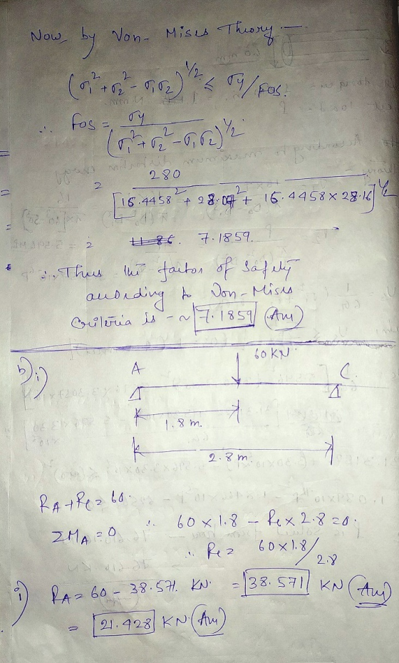
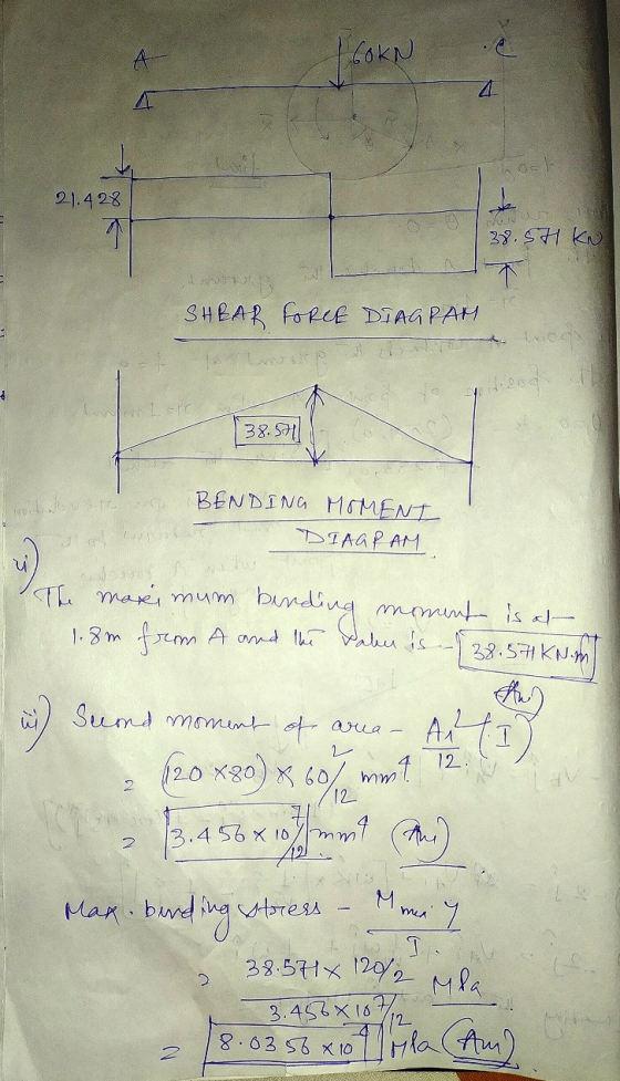
These are the basic questions of strength of materials.The concepts has been laid here properly.Observe it and learn.THANK YOU.
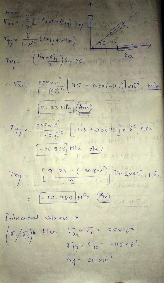
![6.1964 r.). They 175 - 115) x 10 -6 2 (1411510) / 210510 gi 6 10 2 - 2010 I 10 (95) + (105) 1 - 20 1 198. 998] - 20 t 100 50.](http://img.homeworklib.com/questions/4bfa64b0-384c-11eb-8b19-89e01d020c97.png?x-oss-process=image/resize,w_560)
Add Answer to:
Question 2 I (a) Using a 459 strain gauge rosette placed on a mild steel structure,...
Asap 1. The bracket is made of steel (Young's modulus 200 GPa; Poisson's ratio 0.3). When the force P is applied to the bracket, the gages in the strain rosette at point A have the followi...
 Asap
1. The bracket is made of steel (Young's modulus 200 GPa; Poisson's ratio 0.3). When the force P is applied to the bracket, the gages in the strain rosette at point A have the following readings: E.-60 μ . Ep 135 μ l, and E.-264 μ (a) Determine the shear strain at point A. (b) Determine the orientation of the principal plane, the in-plane principal strains, the maximum in-plane shear strain, and the average in-plane normal strain. Determine the...
Asap
1. The bracket is made of steel (Young's modulus 200 GPa; Poisson's ratio 0.3). When the force P is applied to the bracket, the gages in the strain rosette at point A have the following readings: E.-60 μ . Ep 135 μ l, and E.-264 μ (a) Determine the shear strain at point A. (b) Determine the orientation of the principal plane, the in-plane principal strains, the maximum in-plane shear strain, and the average in-plane normal strain. Determine the...
Part A - Question 3 (Total Marks for Part A - Question 3:20) A steel beam...
 Part A - Question 3 (Total Marks for Part A - Question 3:20) A steel beam in an industrial structure is part of a complicated frame that was difficult to analyse. Using a rectangular strain gauge rosette, the actual strains at point A have been recorded while being subjected to test loads. It is necessary to determine the normal stresses and shear stresses in the actual beam subject to the test loads to check whether the stresses assumed in the...
Question 3 For the simply supported steel beam with cross section and loading shown (see Figure...
 Question 3 For the simply supported steel beam with cross section and loading shown (see Figure 3a), knowing that uniformly distributed load w=60 kN/m, Young modulus E = 200 GPa, and yield stress Cyield=200 MPa (in both tension and compression). ул 15 mm w=60 kN/m ... 1 B A 15 mm + 300 mm IC - i 2.5m 1 1 15 mm 7.5m 1 150 mm Figure 3a (a) Check if: the beam is safe with respect to yielding (using...
The beam of building structure (Fig. 3a) is made of mild steel I-section beam with 80mm...
 The beam of building structure (Fig. 3a) is made of mild steel I-section beam with 80mm deep and 60mm wide as shown in Fig. 36. The beam is bolted (simply supported) onto the girder on both side over a span of 1.0 m. The loading from deck is expected to transfer onto the beam as the form of uniform distributed load, w. The material is to be treated as elastic-perfectly plastic, with yield strength of 240 MPa, and elasticity modulus...
The beam of building structure (Fig. 3a) is made of mild steel I-section beam with 80mm...
 The beam of building structure (Fig. 3a) is made of mild steel I-section beam with 80mm deep and 60mm wide as shown in Fig. 36. The beam is bolted (simply supported) onto the girder on both side over a span of 1.0 m. The loading from deck is expected to transfer onto the beam as the form of uniform distributed load, w. The material is to be treated as elastic-perfectly plastic, with yield strength of 240 MPa, and elasticity modulus...
Hi, could you please provide a clear and easy to follow worked solution for the following questions. I will leave feedba...
 Hi,
could you please provide a clear and easy to follow worked
solution for the following questions. I will leave feedback that
reflects the quality of your response.
The correct answers are
21.0kN.m
50.2MPa and 38.7MPa
22.6kN.m
A beam with the section illustrated in the figure below is subjected to pure bending with compressive stresses induced above the neutral axis. The beam is steel with a yield strength of 450 MPa, modulus of elasticity of 210 GPa and Poisson's ratio...
Hi,
could you please provide a clear and easy to follow worked
solution for the following questions. I will leave feedback that
reflects the quality of your response.
The correct answers are
21.0kN.m
50.2MPa and 38.7MPa
22.6kN.m
A beam with the section illustrated in the figure below is subjected to pure bending with compressive stresses induced above the neutral axis. The beam is steel with a yield strength of 450 MPa, modulus of elasticity of 210 GPa and Poisson's ratio...
3. Power transmission is an important engineering application and relies on the integrity of the shaft designs. Assume a solid, circular steel shaft with a uniform diameter d 50 mm and a total le...
 3. Power transmission is an important engineering application and relies on the integrity of the shaft designs. Assume a solid, circular steel shaft with a uniform diameter d 50 mm and a total length I3 m. At its midpoint, a belt passes over a pulley and delivers 50 kW power to the shaft. This power is used to drive two machines at either end of the shaft. Machine 1 consumes P1 20 kW and machine 2 uses P230 KW. The...
20 KN 20 kN/m From the figure load given, the beam AB is I profile (S...
 20 KN 20 kN/m From the figure load given, the beam AB is I profile (S shape, American standard, see appendix) Determine: a) The support force A and C. b) Draw the shear force and bending moment diagram. Write down the value on your diagram c) Determine the size of the I beam, write down (or mark on the I beam table in appendix) the type you choose to the nearest calculation. A B 1.5 m 1.5 m 2.2 m...
Question 2 (30 marks) The wood beam below (cross section dimensions 150 x 250 mm, as...
 Question 2 (30 marks) The wood beam below (cross section dimensions 150 x 250 mm, as indicated) is strengthened at the bottom using 3 steel reinforcement plates of the same 12mm thickness (see figure), perfectly glued to the wooden beam. The modulus of elasticity for wood is E,-12 GPa and for steel E,-200 GPa. Given the allowable stresses (in both tension and compression) for wood ơw-12 MPa and for steel Ơs = 150 MPa, determine the largest possible moment due...
Question 1 (Total 100/3 Marks) Figure 1 (all units are mm) shows a simply supported beam of span ...
 Question 1 (Total 100/3 Marks) Figure 1 (all units are mm) shows a simply supported beam of span 2500 mm with a 5 kN/m load. The cross-section of the beam is a composite section made from two steel plates attached to the top and bottom of a timber section. The top steel plate is 5 mm wide and 20 mm deep. The bottom steel plate is also 5 mm wide but 10 mm deep. The timber section is 50 mm...
 Asap
1. The bracket is made of steel (Young's modulus 200 GPa; Poisson's ratio 0.3). When the force P is applied to the bracket, the gages in the strain rosette at point A have the following readings: E.-60 μ . Ep 135 μ l, and E.-264 μ (a) Determine the shear strain at point A. (b) Determine the orientation of the principal plane, the in-plane principal strains, the maximum in-plane shear strain, and the average in-plane normal strain. Determine the...
Asap
1. The bracket is made of steel (Young's modulus 200 GPa; Poisson's ratio 0.3). When the force P is applied to the bracket, the gages in the strain rosette at point A have the following readings: E.-60 μ . Ep 135 μ l, and E.-264 μ (a) Determine the shear strain at point A. (b) Determine the orientation of the principal plane, the in-plane principal strains, the maximum in-plane shear strain, and the average in-plane normal strain. Determine the...
 Part A - Question 3 (Total Marks for Part A - Question 3:20) A steel beam in an industrial structure is part of a complicated frame that was difficult to analyse. Using a rectangular strain gauge rosette, the actual strains at point A have been recorded while being subjected to test loads. It is necessary to determine the normal stresses and shear stresses in the actual beam subject to the test loads to check whether the stresses assumed in the...
 Question 3 For the simply supported steel beam with cross section and loading shown (see Figure 3a), knowing that uniformly distributed load w=60 kN/m, Young modulus E = 200 GPa, and yield stress Cyield=200 MPa (in both tension and compression). ул 15 mm w=60 kN/m ... 1 B A 15 mm + 300 mm IC - i 2.5m 1 1 15 mm 7.5m 1 150 mm Figure 3a (a) Check if: the beam is safe with respect to yielding (using...
 The beam of building structure (Fig. 3a) is made of mild steel I-section beam with 80mm deep and 60mm wide as shown in Fig. 36. The beam is bolted (simply supported) onto the girder on both side over a span of 1.0 m. The loading from deck is expected to transfer onto the beam as the form of uniform distributed load, w. The material is to be treated as elastic-perfectly plastic, with yield strength of 240 MPa, and elasticity modulus...
 The beam of building structure (Fig. 3a) is made of mild steel I-section beam with 80mm deep and 60mm wide as shown in Fig. 36. The beam is bolted (simply supported) onto the girder on both side over a span of 1.0 m. The loading from deck is expected to transfer onto the beam as the form of uniform distributed load, w. The material is to be treated as elastic-perfectly plastic, with yield strength of 240 MPa, and elasticity modulus...
 Hi,
could you please provide a clear and easy to follow worked
solution for the following questions. I will leave feedback that
reflects the quality of your response.
The correct answers are
21.0kN.m
50.2MPa and 38.7MPa
22.6kN.m
A beam with the section illustrated in the figure below is subjected to pure bending with compressive stresses induced above the neutral axis. The beam is steel with a yield strength of 450 MPa, modulus of elasticity of 210 GPa and Poisson's ratio...
Hi,
could you please provide a clear and easy to follow worked
solution for the following questions. I will leave feedback that
reflects the quality of your response.
The correct answers are
21.0kN.m
50.2MPa and 38.7MPa
22.6kN.m
A beam with the section illustrated in the figure below is subjected to pure bending with compressive stresses induced above the neutral axis. The beam is steel with a yield strength of 450 MPa, modulus of elasticity of 210 GPa and Poisson's ratio...
 3. Power transmission is an important engineering application and relies on the integrity of the shaft designs. Assume a solid, circular steel shaft with a uniform diameter d 50 mm and a total length I3 m. At its midpoint, a belt passes over a pulley and delivers 50 kW power to the shaft. This power is used to drive two machines at either end of the shaft. Machine 1 consumes P1 20 kW and machine 2 uses P230 KW. The...
 20 KN 20 kN/m From the figure load given, the beam AB is I profile (S shape, American standard, see appendix) Determine: a) The support force A and C. b) Draw the shear force and bending moment diagram. Write down the value on your diagram c) Determine the size of the I beam, write down (or mark on the I beam table in appendix) the type you choose to the nearest calculation. A B 1.5 m 1.5 m 2.2 m...
 Question 2 (30 marks) The wood beam below (cross section dimensions 150 x 250 mm, as indicated) is strengthened at the bottom using 3 steel reinforcement plates of the same 12mm thickness (see figure), perfectly glued to the wooden beam. The modulus of elasticity for wood is E,-12 GPa and for steel E,-200 GPa. Given the allowable stresses (in both tension and compression) for wood ơw-12 MPa and for steel Ơs = 150 MPa, determine the largest possible moment due...
 Question 1 (Total 100/3 Marks) Figure 1 (all units are mm) shows a simply supported beam of span 2500 mm with a 5 kN/m load. The cross-section of the beam is a composite section made from two steel plates attached to the top and bottom of a timber section. The top steel plate is 5 mm wide and 20 mm deep. The bottom steel plate is also 5 mm wide but 10 mm deep. The timber section is 50 mm...
Most questions answered within 3 hours.
-
Where is the error in this code sequence?
String s1 = "Hello";
String s2 = "ello";...
asked 11 months ago -
Financial data for Joel de Paris, Inc., for last year
follow:
Joel de Paris, Inc.
Balance...
asked 11 months ago -
Consider this reaction:
Al2(SO4)3 (aq)+ BaCl3
(aq) Al2Cl6 (aq)- +
3BaSO4(s) . What is the...
asked 11 months ago -
Suppose that Savneet is considering increasing her
recent random sample from 20 car rentals to 40...
asked 11 months ago -
Trucks arrive at an unloading terminal at an average rate of 120
per hour.
Trucks arrive...
asked 11 months ago -
Why are methanol and ethanol completely soluble in water while
octanol is not very little soluble....
asked 11 months ago -
A facilities manager at a university reads in a research report
that the mean amount of...
asked 11 months ago -
When the CuSO4 is rehydrated by adding water to the anhydrous
compound, is this an endothermic...
asked 11 months ago -
A ray of sunlight is passing from diamond into crown glass; the
angle of incidence is...
asked 11 months ago -
A block of mass 0.249 kg is placed on top of a light, vertical
spring of...
asked 11 months ago -
how do the kidneys compensate in the presences of acidosis
a) trigger hyperventilate
b) reserve acid...
asked 11 months ago -
Question 501 pts
The rental rate of capital to the firm increases. Which of the
following...
asked 11 months ago