Given the second order filter in figure, with ? = 4 ?Ω, ? = 50 ??, ?1 = 50 nF and ?2 = 1 μF:
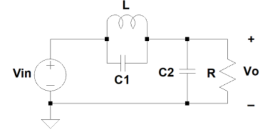
a) Reason the value that the gain of this filter will have for very low frequencies, at the resonance frequency of the parallel LC circuit and for very high frequencies. In the latter case (high frequencies) keep in mind that, since there are two capacitors with a similar asymptotic behavior, we cannot assume that its impedance is null, although it is very low value.
Why do you think this filter is called Low Pass Notch (LPN)?
b) Calculate the normalized network function of the filter ? (?) = ?o(?) ⁄ ?i (?) and, from it, the frequency response of the filter ? (? = ??). Relate this result to those obtained in the previous section.
c) Calculate the bandwidth of the filter.
Homework Answers
Answer :
a.)
The reason that that the value of the gain of this filter will have for very low frequencies, at the resonance frequency of the parallel LC Circuit is that the the capacitor in parallel LC circuit is storing the maximum energy, and the inductor is storing no energy or vice versa .
Due to which the energy is being swapped back and forth between
the capacitor and the inductor, and none is coming from the source
.
As the impedance Z= 0 , the current into the parallel LC
combination is also zero due to which the gain of this filter have
low frequencies . ω<ωο .
This filter can be called as low paas notch Because here the zero frequency is greater than the pole frequency . i.e. (ω0 > ω )
b. ) 


Add Answer to:
Given the second order filter in figure, with ? = 4 ?Ω, ? = 50
??,...
Design the second order band stop filter (notch filter) whose circuit is given below so that...
 Design the second order band stop filter (notch
filter) whose circuit is given below so that the resonance
frequency is 400 Hz and Q = 5 and plot the change of the gain
according to the frequency in the Pspice program and show it on the
parameters of the filter. (Select LM741 for OPAMP.)
(values can be chosen randomly but it must be consistent
pspice is not required. R1 R2 Ra Rb what to choose.
Show that equations
C R₂...
Design the second order band stop filter (notch
filter) whose circuit is given below so that the resonance
frequency is 400 Hz and Q = 5 and plot the change of the gain
according to the frequency in the Pspice program and show it on the
parameters of the filter. (Select LM741 for OPAMP.)
(values can be chosen randomly but it must be consistent
pspice is not required. R1 R2 Ra Rb what to choose.
Show that equations
C R₂...
What is the answer to question 23.1? 23.1 Active low-pass filter You can make a low-pass...
 What is the answer to question
23.1?
23.1 Active low-pass filter You can make a low-pass filter by putting a capacitor Cr and resistor Rf in parallel for Zj as shown in Figure 23.1. At low frequencies (well below the corner frequency), the feedback impedance is approximately Rf and the gain of a non-inverting amplifier is is 1 +R//R,. At high frequencies (well above the corner frequency),the impedance is approx- imately 1/(jwCs), and the gain of a non-inverting amplifier is...
What is the answer to question
23.1?
23.1 Active low-pass filter You can make a low-pass filter by putting a capacitor Cr and resistor Rf in parallel for Zj as shown in Figure 23.1. At low frequencies (well below the corner frequency), the feedback impedance is approximately Rf and the gain of a non-inverting amplifier is is 1 +R//R,. At high frequencies (well above the corner frequency),the impedance is approx- imately 1/(jwCs), and the gain of a non-inverting amplifier is...
8.36 High-pass filter** Consider the setup in Problem 8.13, but with the capacor replaced by an i...
 Problem 8.36 requires reference to 8.13, I only need 8.36
solved
8.36 High-pass filter** Consider the setup in Problem 8.13, but with the capacor replaced by an inductor. Calculate the ratio Ivl2/ Choose values for R and L to make l Vil2 = 0.1 for a 100 Hz signal. This circuit is the most primitive of "high-pass" filters, providing attenuation that increases with decreasing frequency. Show that, for sufficiently low frequencies, the signal power is reduced by a factor 1/4...
Problem 8.36 requires reference to 8.13, I only need 8.36
solved
8.36 High-pass filter** Consider the setup in Problem 8.13, but with the capacor replaced by an inductor. Calculate the ratio Ivl2/ Choose values for R and L to make l Vil2 = 0.1 for a 100 Hz signal. This circuit is the most primitive of "high-pass" filters, providing attenuation that increases with decreasing frequency. Show that, for sufficiently low frequencies, the signal power is reduced by a factor 1/4...
(a) For the circuit of Figure 4, assuming a sinusoidal is(t) (0) Prove that the resonant frequeney is given by o- (3 marks) LC (ii) If the total admittance at resonance is 20 ms (seen by the source)...
 (a) For the circuit of Figure 4, assuming a sinusoidal is(t) (0) Prove that the resonant frequeney is given by o- (3 marks) LC (ii) If the total admittance at resonance is 20 ms (seen by the source) with resonant frequency of wo 5000 rad/s and quality factor of Q-10, calculate the values of R L, C, the bandwidth and half-power frequencies in Hertz. (4 marks) VG and hence show (iii) Derive an expression for the driving point impedance Z(jø)...
4.20 Consider the PLL block diagram of Figure 4-28 with a loop filter having the transfer functio...
 4.20 Consider the PLL block diagram of Figure 4-28 with a loop filter having the transfer function F(s) = K| s + 1.1 a. Determine the value of K that would yield a lock range with an upper bound of 21. b. Determine if the PLL circuit is stable. c.Calculate the PLL bandwidth. few2 4.21 Consider the frequency sythesizer circuit shown in Figure 4-30. The input frequency is 2 GHz and the output frequency is 50 kHz with increments of...
Learning Goal: To analyze and design a passive, first-order low-pass filter using a series RL circuit....
 Learning Goal: To analyze and design a passive, first-order low-pass filter using a series RL circuit. The analysis and design will be repeated for a series RC circuit. An electrocardiogram needs to detect periodic signals of approximately 1 Hz (since the resting heart rate of a healthy adult is between 55 and 70 beats per minute). The instrument operates in an electrical environment that is very noisy with a frequency of 60 Hz. It is desirable to have a low-pass...
2. Consider the given C-R filter. a. (4) Determine the transfer function H(jo) in terms of...
 2. Consider the given C-R filter. a. (4) Determine the transfer function H(jo) in terms of R, C and o. b. (3) Express the transfer function in polar form i.e. find the magnitude and phase expressions. c. (3) Calculate the half-power or cut-off frequency of this filter in rad/s for R = 250 2 and C= 15 nF. d. (4) Plot the magnitude response H(jo) using linear scale. Label both axes. Label maxima, minima, and cut-off frequency points numerically on...
The circuit shown in Figure Q4-1 includes an audio source and the equivalent circuit of a...
 The circuit shown in Figure Q4-1 includes an audio source and the equivalent circuit of a loudspeaker that you have been asked to analyse. 4. a) Assuming the speaker is to operate at a single frequency of 200 Hz and is5 driven by a cosinusoidal signal with peak amplitude of 20 V; determine the equivalent impedance of the speaker When connected to the audio source, calculate the current flow i() When testing the loudspeaker detailed in Q4a) i), you can...
71. A superheterodyne receiver tunes at the frequency range from 25 to 50 MHz. What is the IF frequency of the rece...
 71. A superheterodyne receiver tunes at the frequency range from 25 to 50 MHz. What is the IF frequency of the receiver if the range of the local oscillator is 10 MHz to 35MHz 75. An AM transmitter uses high-level modulation. The RF power amplifier draws 12 A from 22 V supply putting out a carrier power of 140 Watts. What impedance would be seen at the modulation transformer secondary? 72. A receiver has a sensitivity of 0Suv and blocking...
1. Design the common source amplifier shown in Figure 1 with Ip- 1 mA and Vo 5 V Determine V2 and Ri. The MOSFET characteristics are V-50 V, k-0.093 A/V, gate-to- drain capacitance, Cd 40 pF,...
 1. Design the common source amplifier shown in Figure 1 with Ip- 1 mA and Vo 5 V Determine V2 and Ri. The MOSFET characteristics are V-50 V, k-0.093 A/V, gate-to- drain capacitance, Cd 40 pF, and Vi 1.1 V. (For PSpice simulations, use parameters: VTO. 1.1 LAMBDA-002 KP-0.093 CGDO-4E-7 w=100u L-I00u for the 2N7000 MOSFET.) a. Determine the gain and gm of the circuit b. Determine the low-frequency (high-pass response) poles of the common-source amplifier due to the coupling...
 Design the second order band stop filter (notch
filter) whose circuit is given below so that the resonance
frequency is 400 Hz and Q = 5 and plot the change of the gain
according to the frequency in the Pspice program and show it on the
parameters of the filter. (Select LM741 for OPAMP.)
(values can be chosen randomly but it must be consistent
pspice is not required. R1 R2 Ra Rb what to choose.
Show that equations
C R₂...
Design the second order band stop filter (notch
filter) whose circuit is given below so that the resonance
frequency is 400 Hz and Q = 5 and plot the change of the gain
according to the frequency in the Pspice program and show it on the
parameters of the filter. (Select LM741 for OPAMP.)
(values can be chosen randomly but it must be consistent
pspice is not required. R1 R2 Ra Rb what to choose.
Show that equations
C R₂...
 What is the answer to question
23.1?
23.1 Active low-pass filter You can make a low-pass filter by putting a capacitor Cr and resistor Rf in parallel for Zj as shown in Figure 23.1. At low frequencies (well below the corner frequency), the feedback impedance is approximately Rf and the gain of a non-inverting amplifier is is 1 +R//R,. At high frequencies (well above the corner frequency),the impedance is approx- imately 1/(jwCs), and the gain of a non-inverting amplifier is...
What is the answer to question
23.1?
23.1 Active low-pass filter You can make a low-pass filter by putting a capacitor Cr and resistor Rf in parallel for Zj as shown in Figure 23.1. At low frequencies (well below the corner frequency), the feedback impedance is approximately Rf and the gain of a non-inverting amplifier is is 1 +R//R,. At high frequencies (well above the corner frequency),the impedance is approx- imately 1/(jwCs), and the gain of a non-inverting amplifier is...
 Problem 8.36 requires reference to 8.13, I only need 8.36
solved
8.36 High-pass filter** Consider the setup in Problem 8.13, but with the capacor replaced by an inductor. Calculate the ratio Ivl2/ Choose values for R and L to make l Vil2 = 0.1 for a 100 Hz signal. This circuit is the most primitive of "high-pass" filters, providing attenuation that increases with decreasing frequency. Show that, for sufficiently low frequencies, the signal power is reduced by a factor 1/4...
Problem 8.36 requires reference to 8.13, I only need 8.36
solved
8.36 High-pass filter** Consider the setup in Problem 8.13, but with the capacor replaced by an inductor. Calculate the ratio Ivl2/ Choose values for R and L to make l Vil2 = 0.1 for a 100 Hz signal. This circuit is the most primitive of "high-pass" filters, providing attenuation that increases with decreasing frequency. Show that, for sufficiently low frequencies, the signal power is reduced by a factor 1/4...
 (a) For the circuit of Figure 4, assuming a sinusoidal is(t) (0) Prove that the resonant frequeney is given by o- (3 marks) LC (ii) If the total admittance at resonance is 20 ms (seen by the source) with resonant frequency of wo 5000 rad/s and quality factor of Q-10, calculate the values of R L, C, the bandwidth and half-power frequencies in Hertz. (4 marks) VG and hence show (iii) Derive an expression for the driving point impedance Z(jø)...
 4.20 Consider the PLL block diagram of Figure 4-28 with a loop filter having the transfer function F(s) = K| s + 1.1 a. Determine the value of K that would yield a lock range with an upper bound of 21. b. Determine if the PLL circuit is stable. c.Calculate the PLL bandwidth. few2 4.21 Consider the frequency sythesizer circuit shown in Figure 4-30. The input frequency is 2 GHz and the output frequency is 50 kHz with increments of...
 Learning Goal: To analyze and design a passive, first-order low-pass filter using a series RL circuit. The analysis and design will be repeated for a series RC circuit. An electrocardiogram needs to detect periodic signals of approximately 1 Hz (since the resting heart rate of a healthy adult is between 55 and 70 beats per minute). The instrument operates in an electrical environment that is very noisy with a frequency of 60 Hz. It is desirable to have a low-pass...
 2. Consider the given C-R filter. a. (4) Determine the transfer function H(jo) in terms of R, C and o. b. (3) Express the transfer function in polar form i.e. find the magnitude and phase expressions. c. (3) Calculate the half-power or cut-off frequency of this filter in rad/s for R = 250 2 and C= 15 nF. d. (4) Plot the magnitude response H(jo) using linear scale. Label both axes. Label maxima, minima, and cut-off frequency points numerically on...
 The circuit shown in Figure Q4-1 includes an audio source and the equivalent circuit of a loudspeaker that you have been asked to analyse. 4. a) Assuming the speaker is to operate at a single frequency of 200 Hz and is5 driven by a cosinusoidal signal with peak amplitude of 20 V; determine the equivalent impedance of the speaker When connected to the audio source, calculate the current flow i() When testing the loudspeaker detailed in Q4a) i), you can...
 71. A superheterodyne receiver tunes at the frequency range from 25 to 50 MHz. What is the IF frequency of the receiver if the range of the local oscillator is 10 MHz to 35MHz 75. An AM transmitter uses high-level modulation. The RF power amplifier draws 12 A from 22 V supply putting out a carrier power of 140 Watts. What impedance would be seen at the modulation transformer secondary? 72. A receiver has a sensitivity of 0Suv and blocking...
 1. Design the common source amplifier shown in Figure 1 with Ip- 1 mA and Vo 5 V Determine V2 and Ri. The MOSFET characteristics are V-50 V, k-0.093 A/V, gate-to- drain capacitance, Cd 40 pF, and Vi 1.1 V. (For PSpice simulations, use parameters: VTO. 1.1 LAMBDA-002 KP-0.093 CGDO-4E-7 w=100u L-I00u for the 2N7000 MOSFET.) a. Determine the gain and gm of the circuit b. Determine the low-frequency (high-pass response) poles of the common-source amplifier due to the coupling...
Most questions answered within 3 hours.
-
Where is the error in this code sequence?
String s1 = "Hello";
String s2 = "ello";...
asked 10 months ago -
Financial data for Joel de Paris, Inc., for last year
follow:
Joel de Paris, Inc.
Balance...
asked 10 months ago -
Consider this reaction:
Al2(SO4)3 (aq)+ BaCl3
(aq) Al2Cl6 (aq)- +
3BaSO4(s) . What is the...
asked 10 months ago -
Suppose that Savneet is considering increasing her
recent random sample from 20 car rentals to 40...
asked 10 months ago -
Trucks arrive at an unloading terminal at an average rate of 120
per hour.
Trucks arrive...
asked 10 months ago -
Why are methanol and ethanol completely soluble in water while
octanol is not very little soluble....
asked 10 months ago -
A facilities manager at a university reads in a research report
that the mean amount of...
asked 10 months ago -
When the CuSO4 is rehydrated by adding water to the anhydrous
compound, is this an endothermic...
asked 10 months ago -
A ray of sunlight is passing from diamond into crown glass; the
angle of incidence is...
asked 10 months ago -
A block of mass 0.249 kg is placed on top of a light, vertical
spring of...
asked 10 months ago -
how do the kidneys compensate in the presences of acidosis
a) trigger hyperventilate
b) reserve acid...
asked 10 months ago -
Question 501 pts
The rental rate of capital to the firm increases. Which of the
following...
asked 10 months ago