

Homework Answers
I am solving section b)
i) resonance circuits find application in resonance tuning amps.
Parrallel resonance circuits may be used as current amplifr.
Series resonance circuits often can rendered as voltage amplifiers.
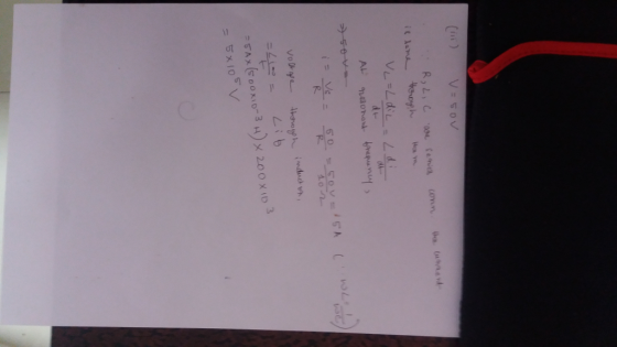
iii)Please refer to fig.
ii) please refer to figure

Add Answer to:
The circuit shown in Figure Q4-1 includes an audio source and the equivalent circuit of a...
11.10 The circuit shown in Fig. P11.10 uses a 12-V ac source to deliver power to...
 11.10 The circuit shown in Fig. P11.10 uses a 12-V ac source to deliver power to an 8-Ω speaker. If the average power delivered to the speaker is 1.8 W at an audio frequency f= 1 kHz, what is the value of the coupling coefficient k? 4Ω 12 cos 2z/t (V) 3mH 12 mH 8Ω Figure P11.10: Circuit for Problem 11.10.
Please Give Me the ANS only Choose the correct answer. 1. An RLC circuit with output...
 Please Give Me the ANS only
Choose the correct answer. 1. An RLC circuit with output on the capacitor is a... a) low pass filter b) high pass filter c) band pass filter d) band stop filter 2. To build a RLC low pass circuit the output has to be taken on... a) the resistor b) the inductor c) the capacitor d) capacitor & inductor 3. In an RLC circuit if R-20092, L=0.9mH and C-40uF what is the value of...
Please Give Me the ANS only
Choose the correct answer. 1. An RLC circuit with output on the capacitor is a... a) low pass filter b) high pass filter c) band pass filter d) band stop filter 2. To build a RLC low pass circuit the output has to be taken on... a) the resistor b) the inductor c) the capacitor d) capacitor & inductor 3. In an RLC circuit if R-20092, L=0.9mH and C-40uF what is the value of...
Problem 4 For the circuit in Fig. 3, frequency w a) Draw the impedance model of the circuit for a source b) Convert the...
 Problem 4 For the circuit in Fig. 3, frequency w a) Draw the impedance model of the circuit for a source b) Convert the voltage lence) and redraw the impedance model; (using Thevenin and Norton equiva- Source into a current source c) Using the results from part (b), derive the expressions to determine the resonance frequency of the circuit in terms of the circuit parameters; e) We would like to have a resonance peak gain frequency of fo equal to...
Figure Q1f) shows the ac equivalent circuit of a common-source amplifier where Rt is the ac load.
 f) Figure Q1f) shows the ac equivalent circuit of a common-source amplifier where Rt is the ac load. The low-frequency roll-off is to be set by the capacitor Cs. Design the amplifier to have a low-frequency roll-off, fL = 100 Hz. You may assume that Rs is much greater than the impedance of Cs at the frequency of 100 Hz. (gm = 1 mA/V) g) The op-amp in Figure Q1g) is ideal. For the condition R1 = R2, show that the...
1. Design a parallel resonant circuit which will meet the following specifications: a. The resonant frequency...
1. Design a parallel resonant circuit which will meet the following specifications: a. The resonant frequency fp is 60 kHz b. The bandwidth is 2700 Hz c. The maximum response is 9 V d. RL = 12 ohm and L = 1 mH for the coil Current source has an internal resistance of 50 Kohm Draw the circuit designed and label it with the component values. . 1. Writing style and organization are very important (Quality not Quantity!). 2. You...
f) Figure Qlf) shows the ac equivalent circuit of a common-source amplifier where have a low-frequeney rol-off C assume that Rs is much greater than the impedance of Cs at the frequency of 100 Re is...
 f) Figure Qlf) shows the ac equivalent circuit of a common-source amplifier where have a low-frequeney rol-off C assume that Rs is much greater than the impedance of Cs at the frequency of 100 Re is the ac load. The low-frequency roll-off is to be set by the capacitor Cs. Design the amplifier to have a low-frequency roll-off, 100 Hz. You may Rt gs gm Vgs V. Rs Cs Figure QiD
f) Figure Qlf) shows the ac equivalent circuit of...
f) Figure Qlf) shows the ac equivalent circuit of a common-source amplifier where have a low-frequeney rol-off C assume that Rs is much greater than the impedance of Cs at the frequency of 100 Re is the ac load. The low-frequency roll-off is to be set by the capacitor Cs. Design the amplifier to have a low-frequency roll-off, 100 Hz. You may Rt gs gm Vgs V. Rs Cs Figure QiD
f) Figure Qlf) shows the ac equivalent circuit of...
3. Consider the AC circuit shown in the figure below, consisting of an alternating voltage source—of...
 3. Consider the AC circuit shown in the figure below, consisting
of an alternating voltage source—of voltage V (t) = V0 cos (ωt)—a
capacitor (of capacitance C), an inductor (of inductance L), and
two resistors (of resistances R1 and R2). Also, note the
highlighted points a and b in the circuit. (a) While explaining
your reasoning, determine the necessary condition that must be
satisfied between the circuit elements such that the potential
difference between points a and b is zero...
3. Consider the AC circuit shown in the figure below, consisting
of an alternating voltage source—of voltage V (t) = V0 cos (ωt)—a
capacitor (of capacitance C), an inductor (of inductance L), and
two resistors (of resistances R1 and R2). Also, note the
highlighted points a and b in the circuit. (a) While explaining
your reasoning, determine the necessary condition that must be
satisfied between the circuit elements such that the potential
difference between points a and b is zero...
please write clearly with steps. thank you Q3. (a) Derive the differential gain for the following equivalent circuit of a differential amplifier. (1o pts) iel el ie RE Ri iel Figure 6. Differentia...
 please write clearly with steps. thank you
Q3. (a) Derive the differential gain for the following equivalent circuit of a differential amplifier. (1o pts) iel el ie RE Ri iel Figure 6. Differential mode small signal equivalent circuit of basic differential amplifier. (b) Given that Ac-0.5 and Ad-9o for a differential amplifier. Find CMRR. (5 pts) (e) Design a first order low pass filter with cut-off frequency of 20 kHz. Assume that pass-band gain is 16dB. You can use Figure...
please write clearly with steps. thank you
Q3. (a) Derive the differential gain for the following equivalent circuit of a differential amplifier. (1o pts) iel el ie RE Ri iel Figure 6. Differential mode small signal equivalent circuit of basic differential amplifier. (b) Given that Ac-0.5 and Ad-9o for a differential amplifier. Find CMRR. (5 pts) (e) Design a first order low pass filter with cut-off frequency of 20 kHz. Assume that pass-band gain is 16dB. You can use Figure...
Design a Sallen-Key circuit as shown in Figure 7.1. Choose component values so that the circuit...
 Design a Sallen-Key circuit as shown in Figure 7.1. Choose
component values so that the circuit produces a critically damped
response (?? = 1/2) and a resonant radian frequency of ??0= 2000??
rad/sec (??0 = 1kHz). Be sure to choose component values that are
available to you in your lab kit. You will not be able to exactly
achieve the design goals with the restrictions of the component
values, but you should try to get as close as possible with...
Design a Sallen-Key circuit as shown in Figure 7.1. Choose
component values so that the circuit produces a critically damped
response (?? = 1/2) and a resonant radian frequency of ??0= 2000??
rad/sec (??0 = 1kHz). Be sure to choose component values that are
available to you in your lab kit. You will not be able to exactly
achieve the design goals with the restrictions of the component
values, but you should try to get as close as possible with...
Hi-fi audio amplifiers are usually built as discrete operational amplifiers with a relatively large gain (g...
 Hi-fi audio amplifiers are usually built as discrete operational
amplifiers with a
relatively large gain (g ? 500) and with feedback that reduces the
closed-loop gain
to a smaller value k = 32. Since loudspeakers predominatly act like
a resistor
(nominal impedance: 8
) with an inductor in series, the feedback network can be
used to improve the frequency response in the audio range up to 20
kHz. We are
primarily concerned with gain and frequency response of the
amplifier....
Hi-fi audio amplifiers are usually built as discrete operational
amplifiers with a
relatively large gain (g ? 500) and with feedback that reduces the
closed-loop gain
to a smaller value k = 32. Since loudspeakers predominatly act like
a resistor
(nominal impedance: 8
) with an inductor in series, the feedback network can be
used to improve the frequency response in the audio range up to 20
kHz. We are
primarily concerned with gain and frequency response of the
amplifier....
 11.10 The circuit shown in Fig. P11.10 uses a 12-V ac source to deliver power to an 8-Ω speaker. If the average power delivered to the speaker is 1.8 W at an audio frequency f= 1 kHz, what is the value of the coupling coefficient k? 4Ω 12 cos 2z/t (V) 3mH 12 mH 8Ω Figure P11.10: Circuit for Problem 11.10.
 Please Give Me the ANS only
Choose the correct answer. 1. An RLC circuit with output on the capacitor is a... a) low pass filter b) high pass filter c) band pass filter d) band stop filter 2. To build a RLC low pass circuit the output has to be taken on... a) the resistor b) the inductor c) the capacitor d) capacitor & inductor 3. In an RLC circuit if R-20092, L=0.9mH and C-40uF what is the value of...
Please Give Me the ANS only
Choose the correct answer. 1. An RLC circuit with output on the capacitor is a... a) low pass filter b) high pass filter c) band pass filter d) band stop filter 2. To build a RLC low pass circuit the output has to be taken on... a) the resistor b) the inductor c) the capacitor d) capacitor & inductor 3. In an RLC circuit if R-20092, L=0.9mH and C-40uF what is the value of...
 Problem 4 For the circuit in Fig. 3, frequency w a) Draw the impedance model of the circuit for a source b) Convert the voltage lence) and redraw the impedance model; (using Thevenin and Norton equiva- Source into a current source c) Using the results from part (b), derive the expressions to determine the resonance frequency of the circuit in terms of the circuit parameters; e) We would like to have a resonance peak gain frequency of fo equal to...
 f) Figure Qlf) shows the ac equivalent circuit of a common-source amplifier where have a low-frequeney rol-off C assume that Rs is much greater than the impedance of Cs at the frequency of 100 Re is the ac load. The low-frequency roll-off is to be set by the capacitor Cs. Design the amplifier to have a low-frequency roll-off, 100 Hz. You may Rt gs gm Vgs V. Rs Cs Figure QiD
f) Figure Qlf) shows the ac equivalent circuit of...
f) Figure Qlf) shows the ac equivalent circuit of a common-source amplifier where have a low-frequeney rol-off C assume that Rs is much greater than the impedance of Cs at the frequency of 100 Re is the ac load. The low-frequency roll-off is to be set by the capacitor Cs. Design the amplifier to have a low-frequency roll-off, 100 Hz. You may Rt gs gm Vgs V. Rs Cs Figure QiD
f) Figure Qlf) shows the ac equivalent circuit of...
 3. Consider the AC circuit shown in the figure below, consisting
of an alternating voltage source—of voltage V (t) = V0 cos (ωt)—a
capacitor (of capacitance C), an inductor (of inductance L), and
two resistors (of resistances R1 and R2). Also, note the
highlighted points a and b in the circuit. (a) While explaining
your reasoning, determine the necessary condition that must be
satisfied between the circuit elements such that the potential
difference between points a and b is zero...
3. Consider the AC circuit shown in the figure below, consisting
of an alternating voltage source—of voltage V (t) = V0 cos (ωt)—a
capacitor (of capacitance C), an inductor (of inductance L), and
two resistors (of resistances R1 and R2). Also, note the
highlighted points a and b in the circuit. (a) While explaining
your reasoning, determine the necessary condition that must be
satisfied between the circuit elements such that the potential
difference between points a and b is zero...
 please write clearly with steps. thank you
Q3. (a) Derive the differential gain for the following equivalent circuit of a differential amplifier. (1o pts) iel el ie RE Ri iel Figure 6. Differential mode small signal equivalent circuit of basic differential amplifier. (b) Given that Ac-0.5 and Ad-9o for a differential amplifier. Find CMRR. (5 pts) (e) Design a first order low pass filter with cut-off frequency of 20 kHz. Assume that pass-band gain is 16dB. You can use Figure...
please write clearly with steps. thank you
Q3. (a) Derive the differential gain for the following equivalent circuit of a differential amplifier. (1o pts) iel el ie RE Ri iel Figure 6. Differential mode small signal equivalent circuit of basic differential amplifier. (b) Given that Ac-0.5 and Ad-9o for a differential amplifier. Find CMRR. (5 pts) (e) Design a first order low pass filter with cut-off frequency of 20 kHz. Assume that pass-band gain is 16dB. You can use Figure...
 Design a Sallen-Key circuit as shown in Figure 7.1. Choose
component values so that the circuit produces a critically damped
response (?? = 1/2) and a resonant radian frequency of ??0= 2000??
rad/sec (??0 = 1kHz). Be sure to choose component values that are
available to you in your lab kit. You will not be able to exactly
achieve the design goals with the restrictions of the component
values, but you should try to get as close as possible with...
Design a Sallen-Key circuit as shown in Figure 7.1. Choose
component values so that the circuit produces a critically damped
response (?? = 1/2) and a resonant radian frequency of ??0= 2000??
rad/sec (??0 = 1kHz). Be sure to choose component values that are
available to you in your lab kit. You will not be able to exactly
achieve the design goals with the restrictions of the component
values, but you should try to get as close as possible with...
 Hi-fi audio amplifiers are usually built as discrete operational
amplifiers with a
relatively large gain (g ? 500) and with feedback that reduces the
closed-loop gain
to a smaller value k = 32. Since loudspeakers predominatly act like
a resistor
(nominal impedance: 8
) with an inductor in series, the feedback network can be
used to improve the frequency response in the audio range up to 20
kHz. We are
primarily concerned with gain and frequency response of the
amplifier....
Hi-fi audio amplifiers are usually built as discrete operational
amplifiers with a
relatively large gain (g ? 500) and with feedback that reduces the
closed-loop gain
to a smaller value k = 32. Since loudspeakers predominatly act like
a resistor
(nominal impedance: 8
) with an inductor in series, the feedback network can be
used to improve the frequency response in the audio range up to 20
kHz. We are
primarily concerned with gain and frequency response of the
amplifier....
Most questions answered within 3 hours.
-
Where is the error in this code sequence?
String s1 = "Hello";
String s2 = "ello";...
asked 10 months ago -
Financial data for Joel de Paris, Inc., for last year
follow:
Joel de Paris, Inc.
Balance...
asked 10 months ago -
Consider this reaction:
Al2(SO4)3 (aq)+ BaCl3
(aq) Al2Cl6 (aq)- +
3BaSO4(s) . What is the...
asked 10 months ago -
Suppose that Savneet is considering increasing her
recent random sample from 20 car rentals to 40...
asked 10 months ago -
Trucks arrive at an unloading terminal at an average rate of 120
per hour.
Trucks arrive...
asked 10 months ago -
Why are methanol and ethanol completely soluble in water while
octanol is not very little soluble....
asked 10 months ago -
A facilities manager at a university reads in a research report
that the mean amount of...
asked 10 months ago -
When the CuSO4 is rehydrated by adding water to the anhydrous
compound, is this an endothermic...
asked 10 months ago -
A ray of sunlight is passing from diamond into crown glass; the
angle of incidence is...
asked 10 months ago -
A block of mass 0.249 kg is placed on top of a light, vertical
spring of...
asked 10 months ago -
how do the kidneys compensate in the presences of acidosis
a) trigger hyperventilate
b) reserve acid...
asked 10 months ago -
Question 501 pts
The rental rate of capital to the firm increases. Which of the
following...
asked 10 months ago