
Homework Answers
Add Answer to:
L2 K/ft 15ft Find the reactions of the frame on the left and 25 K 15...
Find the reactions and draw bending moment and shear force diagram D 0.75 k/ft L2.00 k/ft...
 Find the reactions and draw bending moment and shear force diagram D 0.75 k/ft L2.00 k/ft P 15 k 6 ft 6 ft 6 ft 6 ft 18 ft
Problem 1: Given: The beam with a concentrated load shown below. a 10 ft, b 15 ft. Find: Draw the internal shear fo...
 Problem 1: Given: The beam with a concentrated load shown below. a 10 ft, b 15 ft. Find: Draw the internal shear force and bending moment diagrams. Use the standard sign convention. Draw clear, complete and accurate Free Body Diagrams! 5 k
Problem 1: Given: The beam with a concentrated load shown below. a 10 ft, b 15 ft. Find: Draw the internal shear force and bending moment diagrams. Use the standard sign convention. Draw clear, complete and accurate Free...
Problem 1: Given: The beam with a concentrated load shown below. a 10 ft, b 15 ft. Find: Draw the internal shear force and bending moment diagrams. Use the standard sign convention. Draw clear, complete and accurate Free Body Diagrams! 5 k
Problem 1: Given: The beam with a concentrated load shown below. a 10 ft, b 15 ft. Find: Draw the internal shear force and bending moment diagrams. Use the standard sign convention. Draw clear, complete and accurate Free...
Q4: Using slope-deflection method, determine the reactions of the supports for the frame shown in Figure...
 Q4: Using slope-deflection method, determine the reactions of the supports for the frame shown in Figure (4). Then draw shear and bending moment diagrams for the frame . E is constant 25% 5k/ E D 10 ft B-10k 5 ft ts -20 ft 51 -21 E = constant
Q4: Using slope-deflection method, determine the reactions of the supports for the frame shown in Figure...
 Q4: Using slope-deflection method, determine the
reactions of the supports for the frame shown in Figure (4). Then
draw shear and bending moment diagrams for the frame . E is
constant.
I need it in 30min or 1 h
SA E DI 10 ft B-10 k 5 ft A 20 ft +5 Sft E = constant E
Q4: Using slope-deflection method, determine the
reactions of the supports for the frame shown in Figure (4). Then
draw shear and bending moment diagrams for the frame . E is
constant.
I need it in 30min or 1 h
SA E DI 10 ft B-10 k 5 ft A 20 ft +5 Sft E = constant E
1- For the frame shown below a) Place internal hinges in the frame to make it...
 1- For the frame shown below a) Place internal hinges in the frame to make it determinate (5 points) b) Solve for reaction forces at supports (10 points) c) Draw the shear and moment diagrams for beams DE, EF. (20 points) 3 K/A 2 K/ft D E F 1 10ft B 20 ft 20ft
asap Q4: Using slope-deflection method, determine the reactions of the supports for the frame shown in...
 asap
Q4: Using slope-deflection method, determine the reactions of the supports for the frame shown in Figure (4). Then draw shear and bending moment diagrams for the frame. E is constant. 5k/ft E D 10 ft B-10k 5 ft -20 ft tsa -21 E = constant Fig. (4)
asap
Q4: Using slope-deflection method, determine the reactions of the supports for the frame shown in Figure (4). Then draw shear and bending moment diagrams for the frame. E is constant. 5k/ft E D 10 ft B-10k 5 ft -20 ft tsa -21 E = constant Fig. (4)
Solve the following problems: (25 pts. each) Problem 1 Determine the support reactions then draw the...
 Solve the following problems: (25 pts. each) Problem 1 Determine the support reactions then draw the shear and bending moment diagrams for the beam loaded as shown below P !!K LR4 Problem 2 Determine the support reactions then draw the shear and bending moment diagrams for the beam loaded as shown below 구K 4.5 ,81 7 Problem 3 Determine the support reactions then draw the shear and bending moment diagrams for the beam loaded as shown below. Ptok Problem 4...
Q1: For the frame shown in the Fig. (1), check the determinacy and stability then draw...
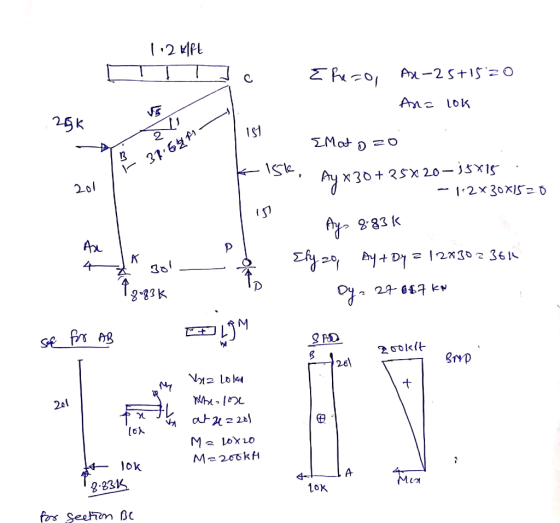
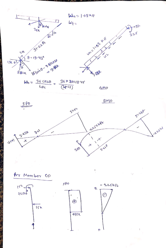
 Q1: For the frame shown in the Fig. (1), check the determinacy and stability then draw the axial force, shearing force, and bending moment diagrams for the frame. 25% 1.2 k/ft Pin OC - 25 k 15 ft 15 k B 20 ft 15 ft D 30 ft Fig. (1)
Q1: For the frame shown in the Fig. (1), check the determinacy and stability then draw...
 Q1: For the frame shown in the Fig. (1), check the determinacy and stability then draw the axial force, shearing force, and bending moment diagrams for the frame. 25% 1.2 k/ft Pin OC 25 k 15 ft 15k B 20 ft 15 ft A 30 ft Fig. (1)
Solve all problems using the finite element stiffness method. For the rigid frame shown in Figure P5-4, determine (1) the nodal displacements and rotation at node 4, (2) the reactions, and (3) the fo...
 Solve all problems using the finite element stiffness method. For the rigid frame shown in Figure P5-4, determine (1) the nodal displacements and rotation at node 4, (2) the reactions, and (3) the forces in each element. Then check equilibrium at node 4 Finally, draw the shear force and bending moment diagrams for each element. Let E 30x 103 ksi, A 8 in2, and I 800 in.4 for all elements. 20 kip 25 ft 25 ft 40 ft Figure P5-4...
 Find the reactions and draw bending moment and shear force diagram D 0.75 k/ft L2.00 k/ft P 15 k 6 ft 6 ft 6 ft 6 ft 18 ft
 Problem 1: Given: The beam with a concentrated load shown below. a 10 ft, b 15 ft. Find: Draw the internal shear force and bending moment diagrams. Use the standard sign convention. Draw clear, complete and accurate Free Body Diagrams! 5 k
Problem 1: Given: The beam with a concentrated load shown below. a 10 ft, b 15 ft. Find: Draw the internal shear force and bending moment diagrams. Use the standard sign convention. Draw clear, complete and accurate Free...
Problem 1: Given: The beam with a concentrated load shown below. a 10 ft, b 15 ft. Find: Draw the internal shear force and bending moment diagrams. Use the standard sign convention. Draw clear, complete and accurate Free Body Diagrams! 5 k
Problem 1: Given: The beam with a concentrated load shown below. a 10 ft, b 15 ft. Find: Draw the internal shear force and bending moment diagrams. Use the standard sign convention. Draw clear, complete and accurate Free...
 Q4: Using slope-deflection method, determine the reactions of the supports for the frame shown in Figure (4). Then draw shear and bending moment diagrams for the frame . E is constant 25% 5k/ E D 10 ft B-10k 5 ft ts -20 ft 51 -21 E = constant
 Q4: Using slope-deflection method, determine the
reactions of the supports for the frame shown in Figure (4). Then
draw shear and bending moment diagrams for the frame . E is
constant.
I need it in 30min or 1 h
SA E DI 10 ft B-10 k 5 ft A 20 ft +5 Sft E = constant E
Q4: Using slope-deflection method, determine the
reactions of the supports for the frame shown in Figure (4). Then
draw shear and bending moment diagrams for the frame . E is
constant.
I need it in 30min or 1 h
SA E DI 10 ft B-10 k 5 ft A 20 ft +5 Sft E = constant E
 1- For the frame shown below a) Place internal hinges in the frame to make it determinate (5 points) b) Solve for reaction forces at supports (10 points) c) Draw the shear and moment diagrams for beams DE, EF. (20 points) 3 K/A 2 K/ft D E F 1 10ft B 20 ft 20ft
 asap
Q4: Using slope-deflection method, determine the reactions of the supports for the frame shown in Figure (4). Then draw shear and bending moment diagrams for the frame. E is constant. 5k/ft E D 10 ft B-10k 5 ft -20 ft tsa -21 E = constant Fig. (4)
asap
Q4: Using slope-deflection method, determine the reactions of the supports for the frame shown in Figure (4). Then draw shear and bending moment diagrams for the frame. E is constant. 5k/ft E D 10 ft B-10k 5 ft -20 ft tsa -21 E = constant Fig. (4)
 Solve the following problems: (25 pts. each) Problem 1 Determine the support reactions then draw the shear and bending moment diagrams for the beam loaded as shown below P !!K LR4 Problem 2 Determine the support reactions then draw the shear and bending moment diagrams for the beam loaded as shown below 구K 4.5 ,81 7 Problem 3 Determine the support reactions then draw the shear and bending moment diagrams for the beam loaded as shown below. Ptok Problem 4...
 Q1: For the frame shown in the Fig. (1), check the determinacy and stability then draw the axial force, shearing force, and bending moment diagrams for the frame. 25% 1.2 k/ft Pin OC - 25 k 15 ft 15 k B 20 ft 15 ft D 30 ft Fig. (1)
 Q1: For the frame shown in the Fig. (1), check the determinacy and stability then draw the axial force, shearing force, and bending moment diagrams for the frame. 25% 1.2 k/ft Pin OC 25 k 15 ft 15k B 20 ft 15 ft A 30 ft Fig. (1)
 Solve all problems using the finite element stiffness method. For the rigid frame shown in Figure P5-4, determine (1) the nodal displacements and rotation at node 4, (2) the reactions, and (3) the forces in each element. Then check equilibrium at node 4 Finally, draw the shear force and bending moment diagrams for each element. Let E 30x 103 ksi, A 8 in2, and I 800 in.4 for all elements. 20 kip 25 ft 25 ft 40 ft Figure P5-4...
Most questions answered within 3 hours.
-
Where is the error in this code sequence?
String s1 = "Hello";
String s2 = "ello";...
asked 11 months ago -
Financial data for Joel de Paris, Inc., for last year
follow:
Joel de Paris, Inc.
Balance...
asked 11 months ago -
Consider this reaction:
Al2(SO4)3 (aq)+ BaCl3
(aq) Al2Cl6 (aq)- +
3BaSO4(s) . What is the...
asked 11 months ago -
Suppose that Savneet is considering increasing her
recent random sample from 20 car rentals to 40...
asked 11 months ago -
Trucks arrive at an unloading terminal at an average rate of 120
per hour.
Trucks arrive...
asked 11 months ago -
Why are methanol and ethanol completely soluble in water while
octanol is not very little soluble....
asked 11 months ago -
A facilities manager at a university reads in a research report
that the mean amount of...
asked 11 months ago -
When the CuSO4 is rehydrated by adding water to the anhydrous
compound, is this an endothermic...
asked 11 months ago -
A ray of sunlight is passing from diamond into crown glass; the
angle of incidence is...
asked 11 months ago -
A block of mass 0.249 kg is placed on top of a light, vertical
spring of...
asked 11 months ago -
how do the kidneys compensate in the presences of acidosis
a) trigger hyperventilate
b) reserve acid...
asked 11 months ago -
Question 501 pts
The rental rate of capital to the firm increases. Which of the
following...
asked 11 months ago