
Homework Answers


Add Answer to:
1- For the frame shown below a) Place internal hinges in the frame to make it...
Problem: for the frame below, assume that E-30,000 ksi for all beams and columns. Also assume tha...
 Problem: for the frame below, assume that E-30,000 ksi for all beams and columns. Also assume that beams have the size of W24x84 for the two stories, W21x50 for the third story, and W14x211 for all the columns 15 ft 8 k 30 ft 20 ft+--20 ft--t-30 ft Part a: use the portal method to solve the reaction forces and the moment diagram of the frame. (15%) Part b: the horizontal displacement of points T, O and J; (20%)
Problem:...
Problem: for the frame below, assume that E-30,000 ksi for all beams and columns. Also assume that beams have the size of W24x84 for the two stories, W21x50 for the third story, and W14x211 for all the columns 15 ft 8 k 30 ft 20 ft+--20 ft--t-30 ft Part a: use the portal method to solve the reaction forces and the moment diagram of the frame. (15%) Part b: the horizontal displacement of points T, O and J; (20%)
Problem:...
1. (60 points) Draw axial, shear, and bending moment diagrams for the frame shown below. Draw...
 1. (60 points) Draw axial, shear, and bending moment diagrams for the frame shown below. Draw one set of P, V, and M diagrams for Column AB, one set for Beam BE, and one set for Column DF. There is a fixed support at A and applied forces and moments as shown below. 500 lb 500 lb 5 k-ft 5 k-ft D 5 k-ft B 10 10' 10' E 500 lb/ft 10' 10' 5k s tiskt 5 k-ft 1k 2....
L2 K/ft 15ft Find the reactions of the frame on the left and 25 K 15...
 L2 K/ft 15ft Find the reactions of the frame on the left and 25 K 15 K draw the shear and bending moment diagrams. 20ft 15ft -30A-
Q4: Using slope-deflection method, determine the reactions of the supports for the frame shown in Figure...
 Q4: Using slope-deflection method, determine the
reactions of the supports for the frame shown in Figure (4). Then
draw shear and bending moment diagrams for the frame . E is
constant.
I need it in 30min or 1 h
SA E DI 10 ft B-10 k 5 ft A 20 ft +5 Sft E = constant E
Q4: Using slope-deflection method, determine the
reactions of the supports for the frame shown in Figure (4). Then
draw shear and bending moment diagrams for the frame . E is
constant.
I need it in 30min or 1 h
SA E DI 10 ft B-10 k 5 ft A 20 ft +5 Sft E = constant E
1.2 m 0.1 m (5) In the frame shown, find the reaction forces at A and...
 1.2 m 0.1 m (5) In the frame shown, find the reaction forces at A and C, if the cylinder’s mass is 50 kg. i 0.3 m 0.6 m 50 lb/ft I 200 16.ft A B- 1 Q6) For the beam shown, draw the shear and moment diagrams and find the magnitude and location of the maximum moment. -20 ft -10 ft
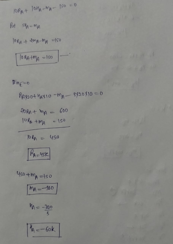
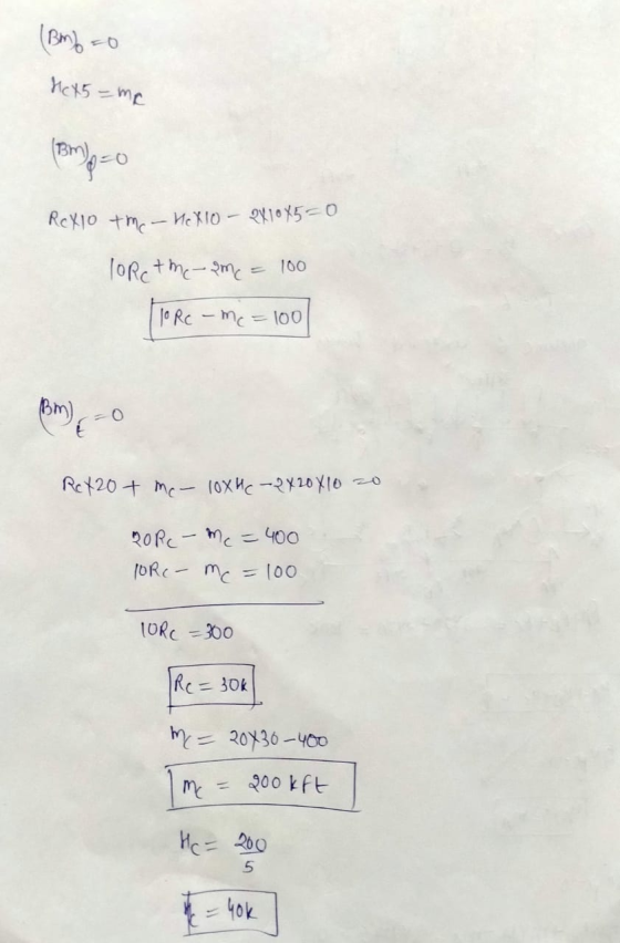
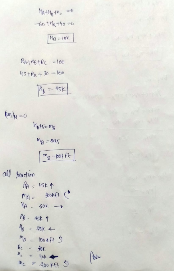
Problem 3.(4 points) For the determinate frame shown below calculate the reactions and draw the final...
 Problem 3.(4 points) For the determinate frame shown below calculate the reactions and draw the final shear, moment, and deflected shape diagrams /y HiNGe
Q4: Using slope-deflection method, determine the reactions of the supports for the frame shown in Figure...
 Q4: Using slope-deflection method, determine the reactions of the supports for the frame shown in Figure (4). Then draw shear and bending moment diagrams for the frame . E is constant 25% 5k/ E D 10 ft B-10k 5 ft ts -20 ft 51 -21 E = constant
1) Determine the reactions at the supports for the structures shown. The support at A is...
 1) Determine the reactions at the supports for the structures shown. The support at A is a Roller and the support at B is a Pin. 2.0 k/ft M 10 k- 3.0 k/ft 12 ft 25 k- 25k-Pokift 15 ft B! 1 F20ft- 2) 2 3 k/ft A beam is supported at points A, C, and E, and is loaded as shown. The support at A is fixed. The supports at C and E are rollers. Hinge-B ce Dl Hinge...
asap Q4: Using slope-deflection method, determine the reactions of the supports for the frame shown in...
 asap
Q4: Using slope-deflection method, determine the reactions of the supports for the frame shown in Figure (4). Then draw shear and bending moment diagrams for the frame. E is constant. 5k/ft E D 10 ft B-10k 5 ft -20 ft tsa -21 E = constant Fig. (4)
asap
Q4: Using slope-deflection method, determine the reactions of the supports for the frame shown in Figure (4). Then draw shear and bending moment diagrams for the frame. E is constant. 5k/ft E D 10 ft B-10k 5 ft -20 ft tsa -21 E = constant Fig. (4)
Draw the shear and moment diagrams for the beam shown below. NOT THE FRAME!
 Draw the shear and moment diagrams for the beam shown
below. NOT THE FRAME! Find the internal resisting forces at: Middle of AB Middle of BC Middle of CD
Draw the shear and moment diagrams for the beam shown
below. NOT THE FRAME! Find the internal resisting forces at: Middle of AB Middle of BC Middle of CD
 Problem: for the frame below, assume that E-30,000 ksi for all beams and columns. Also assume that beams have the size of W24x84 for the two stories, W21x50 for the third story, and W14x211 for all the columns 15 ft 8 k 30 ft 20 ft+--20 ft--t-30 ft Part a: use the portal method to solve the reaction forces and the moment diagram of the frame. (15%) Part b: the horizontal displacement of points T, O and J; (20%)
Problem:...
Problem: for the frame below, assume that E-30,000 ksi for all beams and columns. Also assume that beams have the size of W24x84 for the two stories, W21x50 for the third story, and W14x211 for all the columns 15 ft 8 k 30 ft 20 ft+--20 ft--t-30 ft Part a: use the portal method to solve the reaction forces and the moment diagram of the frame. (15%) Part b: the horizontal displacement of points T, O and J; (20%)
Problem:...
 1. (60 points) Draw axial, shear, and bending moment diagrams for the frame shown below. Draw one set of P, V, and M diagrams for Column AB, one set for Beam BE, and one set for Column DF. There is a fixed support at A and applied forces and moments as shown below. 500 lb 500 lb 5 k-ft 5 k-ft D 5 k-ft B 10 10' 10' E 500 lb/ft 10' 10' 5k s tiskt 5 k-ft 1k 2....
 L2 K/ft 15ft Find the reactions of the frame on the left and 25 K 15 K draw the shear and bending moment diagrams. 20ft 15ft -30A-
 Q4: Using slope-deflection method, determine the
reactions of the supports for the frame shown in Figure (4). Then
draw shear and bending moment diagrams for the frame . E is
constant.
I need it in 30min or 1 h
SA E DI 10 ft B-10 k 5 ft A 20 ft +5 Sft E = constant E
Q4: Using slope-deflection method, determine the
reactions of the supports for the frame shown in Figure (4). Then
draw shear and bending moment diagrams for the frame . E is
constant.
I need it in 30min or 1 h
SA E DI 10 ft B-10 k 5 ft A 20 ft +5 Sft E = constant E
 1.2 m 0.1 m (5) In the frame shown, find the reaction forces at A and C, if the cylinder’s mass is 50 kg. i 0.3 m 0.6 m 50 lb/ft I 200 16.ft A B- 1 Q6) For the beam shown, draw the shear and moment diagrams and find the magnitude and location of the maximum moment. -20 ft -10 ft
 Problem 3.(4 points) For the determinate frame shown below calculate the reactions and draw the final shear, moment, and deflected shape diagrams /y HiNGe
 Q4: Using slope-deflection method, determine the reactions of the supports for the frame shown in Figure (4). Then draw shear and bending moment diagrams for the frame . E is constant 25% 5k/ E D 10 ft B-10k 5 ft ts -20 ft 51 -21 E = constant
 1) Determine the reactions at the supports for the structures shown. The support at A is a Roller and the support at B is a Pin. 2.0 k/ft M 10 k- 3.0 k/ft 12 ft 25 k- 25k-Pokift 15 ft B! 1 F20ft- 2) 2 3 k/ft A beam is supported at points A, C, and E, and is loaded as shown. The support at A is fixed. The supports at C and E are rollers. Hinge-B ce Dl Hinge...
 asap
Q4: Using slope-deflection method, determine the reactions of the supports for the frame shown in Figure (4). Then draw shear and bending moment diagrams for the frame. E is constant. 5k/ft E D 10 ft B-10k 5 ft -20 ft tsa -21 E = constant Fig. (4)
asap
Q4: Using slope-deflection method, determine the reactions of the supports for the frame shown in Figure (4). Then draw shear and bending moment diagrams for the frame. E is constant. 5k/ft E D 10 ft B-10k 5 ft -20 ft tsa -21 E = constant Fig. (4)
 Draw the shear and moment diagrams for the beam shown
below. NOT THE FRAME! Find the internal resisting forces at: Middle of AB Middle of BC Middle of CD
Draw the shear and moment diagrams for the beam shown
below. NOT THE FRAME! Find the internal resisting forces at: Middle of AB Middle of BC Middle of CD
Most questions answered within 3 hours.
-
Where is the error in this code sequence?
String s1 = "Hello";
String s2 = "ello";...
asked 10 months ago -
Financial data for Joel de Paris, Inc., for last year
follow:
Joel de Paris, Inc.
Balance...
asked 10 months ago -
Consider this reaction:
Al2(SO4)3 (aq)+ BaCl3
(aq) Al2Cl6 (aq)- +
3BaSO4(s) . What is the...
asked 10 months ago -
Suppose that Savneet is considering increasing her
recent random sample from 20 car rentals to 40...
asked 10 months ago -
Trucks arrive at an unloading terminal at an average rate of 120
per hour.
Trucks arrive...
asked 10 months ago -
Why are methanol and ethanol completely soluble in water while
octanol is not very little soluble....
asked 10 months ago -
A facilities manager at a university reads in a research report
that the mean amount of...
asked 10 months ago -
When the CuSO4 is rehydrated by adding water to the anhydrous
compound, is this an endothermic...
asked 10 months ago -
A ray of sunlight is passing from diamond into crown glass; the
angle of incidence is...
asked 10 months ago -
A block of mass 0.249 kg is placed on top of a light, vertical
spring of...
asked 10 months ago -
how do the kidneys compensate in the presences of acidosis
a) trigger hyperventilate
b) reserve acid...
asked 10 months ago -
Question 501 pts
The rental rate of capital to the firm increases. Which of the
following...
asked 10 months ago