
Homework Answers
Hello,
Please find
the answer attached as under. Please give a thumbs up rating if you
find the answer useful! Have a rocking day ahead!
. A block diagram of the system with an observer and a full state feedback is shown below:

An observer is designed so that the states which are not available for measurement are estimated. The estimated states are then taken as input to the state feedback controller to enable a full state feedback law.
b. The state feedback law is designed via Matlab:
*********** Matlab Code *************
sys = tf(1,[10 1 0]);
[A,B,C,D] = tf2ss(1,[10 1 0]);
p1 = -1-1i;
p2 = -1+1i;
K = place(A,B,[p1 p2])
sys_cl = ss(A-B*K,B,C,D);
step(sys_cl);
grid;
xlabel('Time (sec)')
ylabel('Amplitude (m)')
********* End of Code *****
Output:
K =
1.9000 2.0000
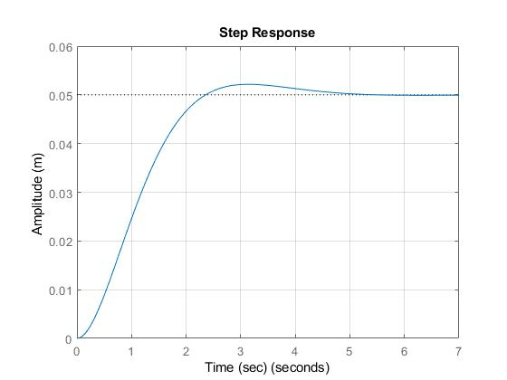
Step response after state feedback:
*****************************************************************
PS: Please do
not forget the thumbs up
Add Answer to:
14. Consider the solar tracking servo with the following transfer function G,(s) = s(10s +1) G...
Consider the following transfer function of a linear control system 1- Determine the state feedb...
 Consider the following transfer function of a linear control
system
1- Determine the state feedback gain matrix that places the
closed system at s=-32, -3.234 ± j3.3.
2- Design a full order observer which produces a set of desired
closed loop poles at s=-16, -16.15±j16.5
3-Assume X1 is measurable, design a reduced order observer with
desired closed loop poles at -16.15±j16.5
We were unable to transcribe this image1 Y(s) U(s) (s+1)(s2+0.7s+2) Consider the following transfer function of a linear control...
Consider the following transfer function of a linear control
system
1- Determine the state feedback gain matrix that places the
closed system at s=-32, -3.234 ± j3.3.
2- Design a full order observer which produces a set of desired
closed loop poles at s=-16, -16.15±j16.5
3-Assume X1 is measurable, design a reduced order observer with
desired closed loop poles at -16.15±j16.5
We were unable to transcribe this image1 Y(s) U(s) (s+1)(s2+0.7s+2) Consider the following transfer function of a linear control...
Consider the following transfer function of a linear control system Determine the state feedba...
 Consider the following transfer function of a linear control
system
Determine the state feedback gain matrix that places the closed
system at s=-32, -3.234 ± j3.3.
Design a full order observer which produces a set of desired
closed loop poles at s=-16, -16.15±j16.5
Assume X1 is measurable, design a reduced order observer with
desired closed loop poles at -16.15±j16.5
We were unable to transcribe this image1 Y(s) U(s) (s+1)(s2+0.7s+2) Consider the following transfer function of a linear control system (a)...
Consider the following transfer function of a linear control
system
Determine the state feedback gain matrix that places the closed
system at s=-32, -3.234 ± j3.3.
Design a full order observer which produces a set of desired
closed loop poles at s=-16, -16.15±j16.5
Assume X1 is measurable, design a reduced order observer with
desired closed loop poles at -16.15±j16.5
We were unable to transcribe this image1 Y(s) U(s) (s+1)(s2+0.7s+2) Consider the following transfer function of a linear control system (a)...
- 4. Full State Feedback and Observer Design Consider the plant s + 1 G(s)- (s + a(s +8(s +10) where a-1. a) Find a...
 - 4. Full State Feedback and Observer Design Consider the plant s + 1 G(s)- (s + a(s +8(s +10) where a-1. a) Find a convenient state space representation of model G(s) . b) Using place design a controller for the system that puts the poles at -1 and-2 +-2 . c) Using place design an observer with poles at-10,-11 and-12 d) Simulate the states with the state estimates overlaid e)Find a state space representation of the closed loop system...
7. For a negative feedback control system with unit feedback gain, its open-loop 100 transfer function...
 7. For a negative feedback control system with unit feedback gain, its open-loop 100 transfer function is G (s) Design a PID controller, so that the open s(10s) corresponding closed-loop poles are -2+jl and -5. (10 scores)
7. For a negative feedback control system with unit feedback gain, its open-loop 100 transfer function is G (s) Design a PID controller, so that the open s(10s) corresponding closed-loop poles are -2+jl and -5. (10 scores)
7. For a negative feedback control system with unit feedback gain, its open-loop 100 transfer function is G (s) Design a PID controller, so that the open s(10s) corresponding closed-loop poles are -2+jl and -5. (10 scores)
Consider the closed loop system defined by the following block diagram. a) Compute the transfer function...
 Consider the closed loop system defined by the following block diagram. a) Compute the transfer function E(s)/R(s). b) Determine the steady state error for a unit-step 1. Controller ant Itly Ro- +- HI- 4단Toy , c) d) e) reference input signal. Determine the steady state error response for a unit-ramp reference input signal. Determine the locations of the closed loop poles of the system. Select system parameters kp and ki in terms of k so that damping coefficient V2/2 and...
Consider the following system: -1-2-21 гг 1 0 1 L Where u is the system input and y is the measur...
 control system with observer
Consider the following system: -1-2-21 гг 1 0 1 L Where u is the system input and y is the measured output. 1. Find the transfer function of the system. 2. Design a state feedback controller with a full-state observer such that the step response of the closed loop system is second order dominant with an overshoot Mp settling time ts s 5 sec. Represent the observer-based control system in a compact state space form. 10%...
control system with observer
Consider the following system: -1-2-21 гг 1 0 1 L Where u is the system input and y is the measured output. 1. Find the transfer function of the system. 2. Design a state feedback controller with a full-state observer such that the step response of the closed loop system is second order dominant with an overshoot Mp settling time ts s 5 sec. Represent the observer-based control system in a compact state space form. 10%...
5. A milling machine has the following open-loop transfer function: (s 1)(s+3) Draw a block diagram describing a negati...
 5. A milling machine has the following open-loop transfer function: (s 1)(s+3) Draw a block diagram describing a negative feedback system that includes a plant a) with transfer function of Gi(s) and a cascade proportional controller with a gain of K. b) Write the closed-loop transfer function for such a negative feedback system c The plant has poles that are solutions to P(s) 0 and zeros that are the solutions to Z(s)-0. Write an equation involving K, P(s) and Z(s)...
Consider a two-tank system, where x, is the level of the first tank, and x2 is the level of the second tank. This dynamic system is described by the -xj-x2. The output to be Q4. following model: dt c...
 Consider a two-tank system, where x, is the level of the first tank, and x2 is the level of the second tank. This dynamic system is described by the -xj-x2. The output to be Q4. following model: dt controlled is the level of the second tank. (a)Write down the state-space model in matrix form. Verify the 20% (b)Design a state feedback controller so that the closed-loop poles are 25% controllability of the system located at -3 and -4 (c) The...
The transfer function of a linear system is G(s) = Y(s) S-1 U(s) 5? + 4s...
 The transfer function of a linear system is G(s) = Y(s) S-1 U(s) 5? + 4s +3 a. Express this system in the modal form. b. Express this system in the standard controllable form (SCF). (Parts d, e, f, and g use this system) c. In the standard controllable form, suppose the output is replaced by y=[-1 a] | [x2] Give a value for a which makes the system unobservable. d. What is y(t) if y(0-)=-3, ay = 6 and...
y(s) 2 u(s) s1 -. Consider the open-loop unstable system G(s) integral controller to regulate the output y to a constant reference r. The desired closed-loop transfer function is G) +16s +100 Design...
 y(s) 2 u(s) s1 -. Consider the open-loop unstable system G(s) integral controller to regulate the output y to a constant reference r. The desired closed-loop transfer function is G) +16s +100 Design the simplest output feedback (20 pts)
y(s) 2 u(s) s1 -. Consider the open-loop unstable system G(s) integral controller to regulate the output y to a constant reference r. The desired closed-loop transfer function is G) +16s +100 Design the simplest output feedback (20 pts)
y(s) 2 u(s) s1 -. Consider the open-loop unstable system G(s) integral controller to regulate the output y to a constant reference r. The desired closed-loop transfer function is G) +16s +100 Design the simplest output feedback (20 pts)
 Consider the following transfer function of a linear control
system
1- Determine the state feedback gain matrix that places the
closed system at s=-32, -3.234 ± j3.3.
2- Design a full order observer which produces a set of desired
closed loop poles at s=-16, -16.15±j16.5
3-Assume X1 is measurable, design a reduced order observer with
desired closed loop poles at -16.15±j16.5
We were unable to transcribe this image1 Y(s) U(s) (s+1)(s2+0.7s+2) Consider the following transfer function of a linear control...
Consider the following transfer function of a linear control
system
1- Determine the state feedback gain matrix that places the
closed system at s=-32, -3.234 ± j3.3.
2- Design a full order observer which produces a set of desired
closed loop poles at s=-16, -16.15±j16.5
3-Assume X1 is measurable, design a reduced order observer with
desired closed loop poles at -16.15±j16.5
We were unable to transcribe this image1 Y(s) U(s) (s+1)(s2+0.7s+2) Consider the following transfer function of a linear control...
 Consider the following transfer function of a linear control
system
Determine the state feedback gain matrix that places the closed
system at s=-32, -3.234 ± j3.3.
Design a full order observer which produces a set of desired
closed loop poles at s=-16, -16.15±j16.5
Assume X1 is measurable, design a reduced order observer with
desired closed loop poles at -16.15±j16.5
We were unable to transcribe this image1 Y(s) U(s) (s+1)(s2+0.7s+2) Consider the following transfer function of a linear control system (a)...
Consider the following transfer function of a linear control
system
Determine the state feedback gain matrix that places the closed
system at s=-32, -3.234 ± j3.3.
Design a full order observer which produces a set of desired
closed loop poles at s=-16, -16.15±j16.5
Assume X1 is measurable, design a reduced order observer with
desired closed loop poles at -16.15±j16.5
We were unable to transcribe this image1 Y(s) U(s) (s+1)(s2+0.7s+2) Consider the following transfer function of a linear control system (a)...
 - 4. Full State Feedback and Observer Design Consider the plant s + 1 G(s)- (s + a(s +8(s +10) where a-1. a) Find a convenient state space representation of model G(s) . b) Using place design a controller for the system that puts the poles at -1 and-2 +-2 . c) Using place design an observer with poles at-10,-11 and-12 d) Simulate the states with the state estimates overlaid e)Find a state space representation of the closed loop system...
 7. For a negative feedback control system with unit feedback gain, its open-loop 100 transfer function is G (s) Design a PID controller, so that the open s(10s) corresponding closed-loop poles are -2+jl and -5. (10 scores)
7. For a negative feedback control system with unit feedback gain, its open-loop 100 transfer function is G (s) Design a PID controller, so that the open s(10s) corresponding closed-loop poles are -2+jl and -5. (10 scores)
7. For a negative feedback control system with unit feedback gain, its open-loop 100 transfer function is G (s) Design a PID controller, so that the open s(10s) corresponding closed-loop poles are -2+jl and -5. (10 scores)
 Consider the closed loop system defined by the following block diagram. a) Compute the transfer function E(s)/R(s). b) Determine the steady state error for a unit-step 1. Controller ant Itly Ro- +- HI- 4단Toy , c) d) e) reference input signal. Determine the steady state error response for a unit-ramp reference input signal. Determine the locations of the closed loop poles of the system. Select system parameters kp and ki in terms of k so that damping coefficient V2/2 and...
 control system with observer
Consider the following system: -1-2-21 гг 1 0 1 L Where u is the system input and y is the measured output. 1. Find the transfer function of the system. 2. Design a state feedback controller with a full-state observer such that the step response of the closed loop system is second order dominant with an overshoot Mp settling time ts s 5 sec. Represent the observer-based control system in a compact state space form. 10%...
control system with observer
Consider the following system: -1-2-21 гг 1 0 1 L Where u is the system input and y is the measured output. 1. Find the transfer function of the system. 2. Design a state feedback controller with a full-state observer such that the step response of the closed loop system is second order dominant with an overshoot Mp settling time ts s 5 sec. Represent the observer-based control system in a compact state space form. 10%...
 5. A milling machine has the following open-loop transfer function: (s 1)(s+3) Draw a block diagram describing a negative feedback system that includes a plant a) with transfer function of Gi(s) and a cascade proportional controller with a gain of K. b) Write the closed-loop transfer function for such a negative feedback system c The plant has poles that are solutions to P(s) 0 and zeros that are the solutions to Z(s)-0. Write an equation involving K, P(s) and Z(s)...
 Consider a two-tank system, where x, is the level of the first tank, and x2 is the level of the second tank. This dynamic system is described by the -xj-x2. The output to be Q4. following model: dt controlled is the level of the second tank. (a)Write down the state-space model in matrix form. Verify the 20% (b)Design a state feedback controller so that the closed-loop poles are 25% controllability of the system located at -3 and -4 (c) The...
 The transfer function of a linear system is G(s) = Y(s) S-1 U(s) 5? + 4s +3 a. Express this system in the modal form. b. Express this system in the standard controllable form (SCF). (Parts d, e, f, and g use this system) c. In the standard controllable form, suppose the output is replaced by y=[-1 a] | [x2] Give a value for a which makes the system unobservable. d. What is y(t) if y(0-)=-3, ay = 6 and...
 y(s) 2 u(s) s1 -. Consider the open-loop unstable system G(s) integral controller to regulate the output y to a constant reference r. The desired closed-loop transfer function is G) +16s +100 Design the simplest output feedback (20 pts)
y(s) 2 u(s) s1 -. Consider the open-loop unstable system G(s) integral controller to regulate the output y to a constant reference r. The desired closed-loop transfer function is G) +16s +100 Design the simplest output feedback (20 pts)
y(s) 2 u(s) s1 -. Consider the open-loop unstable system G(s) integral controller to regulate the output y to a constant reference r. The desired closed-loop transfer function is G) +16s +100 Design the simplest output feedback (20 pts)
Most questions answered within 3 hours.
-
Where is the error in this code sequence?
String s1 = "Hello";
String s2 = "ello";...
asked 11 months ago -
Financial data for Joel de Paris, Inc., for last year
follow:
Joel de Paris, Inc.
Balance...
asked 11 months ago -
Consider this reaction:
Al2(SO4)3 (aq)+ BaCl3
(aq) Al2Cl6 (aq)- +
3BaSO4(s) . What is the...
asked 11 months ago -
Suppose that Savneet is considering increasing her
recent random sample from 20 car rentals to 40...
asked 11 months ago -
Trucks arrive at an unloading terminal at an average rate of 120
per hour.
Trucks arrive...
asked 11 months ago -
Why are methanol and ethanol completely soluble in water while
octanol is not very little soluble....
asked 11 months ago -
A facilities manager at a university reads in a research report
that the mean amount of...
asked 11 months ago -
When the CuSO4 is rehydrated by adding water to the anhydrous
compound, is this an endothermic...
asked 11 months ago -
A ray of sunlight is passing from diamond into crown glass; the
angle of incidence is...
asked 11 months ago -
A block of mass 0.249 kg is placed on top of a light, vertical
spring of...
asked 11 months ago -
how do the kidneys compensate in the presences of acidosis
a) trigger hyperventilate
b) reserve acid...
asked 11 months ago -
Question 501 pts
The rental rate of capital to the firm increases. Which of the
following...
asked 11 months ago