
Homework Answers

Add Answer to:
(25 pts) 5. The state diagram of a synchronous sequential circuit is shown below. X is...
HW#4-SYNCHRONOUS SEQUENTIAL CIRCUIT DESIGN Given the following state diagram, obtain the corresponding synchronous sequential circuit with...
 HW#4-SYNCHRONOUS SEQUENTIAL CIRCUIT DESIGN Given the following state diagram, obtain the corresponding synchronous sequential circuit with D flip-flops. Draw this circuit. (Use x as an input, and z as an output). 50 points] 1) 1/0 0/0 1/0
1. Given the state diagram shown below for a two-state synchronous sequential Mealy circuit with input....
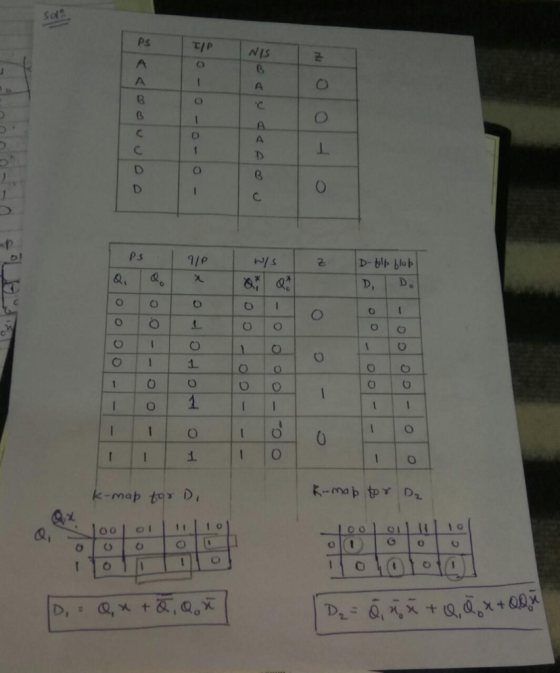
 1. Given the state diagram shown below for a two-state synchronous sequential Mealy circuit with input. and output z, realize the circuit using D flip-flops. Your answer must include the state transition,excita- tion, and output tables, the excitation equation(s), and a labeled circuit diagram 1/0 2. Given the state diagram in Problem 1, realize the circuit using JK flip-flops. Your answer must include the state transition, excitation, and output tables, the excitation equation(s), and a labeled circuit diagram. 3. Given...
5) A single-input (x) single-output(z) synchronous sequential circuit is required to operate as follows: i) The...
 5) A single-input (x) single-output(z) synchronous sequential circuit is required to operate as follows: i) The circuit is put to a specific initial state (call this state A) ii) Starting from state A, the circuit will give a 1 output when the input sequence up to and including the present time contains an odd number of 0's and an odd number of l's: the circuit will give a 0 output at all other times An example input and corresponding output...
Draw a Moore-type state diagram and design a synchronous sequential circuit using D flip flops for...
Draw a Moore-type state diagram and design a synchronous sequential circuit using D flip flops for a 1-input/1-output "sequence detector" for the sequence 110 (be sure to recognize overlapping sequences). Draw the final circuit.
Draw a Moore-type state diagram and design a synchronous sequential circuit using D flip flops for...
Draw a Moore-type state diagram and design a synchronous sequential circuit using D flip flops for a 1-input/1-output "sequence detector" for the sequence 1001 (be sure to recognize overlapping sequences). Draw the final circuit.
Draw the Logic diagram and the state transition diagram for a sequential circuit with two T...
Draw the Logic diagram and the state transition diagram for a sequential circuit with two T flip-flops, FFA and FFB; one input X, with flip-flop inputs TA=XA+XB, TB=XA’, and output Z=X’(A+B).
Thc state transition table bclow is for a sequential circuit with onc input X and onc output Y. The circuit has two state variables A and B, and synchronous input Reset that resets the circuit to sta...
 Thc state transition table bclow is for a sequential circuit with onc input X and onc output Y. The circuit has two state variables A and B, and synchronous input Reset that resets the circuit to state AB-01 when Reset 1: Present State Next State Output X-0 A B A B 0 Reset State 0 0 (9 points) Implement the sequential circuit using minimum number of logic gates and rising- edge triggered D-FFs and draw the logic diagram of the...
Design a synchronous sequential counter circuit that has the state diagram shown in figure 1. Use...
 Design a synchronous sequential counter circuit that has the state diagram shown in figure 1. Use both D-type and T-type Flip Flops in your design. Show all your work in details. Extra credit will be given for implementation using other types of Flip Flops 3 4 Figure 1 Deliverables: 1. State Transition Table 2. K-Maps 3. Logical Expressions (Minimal Form) 4. Schematic Diagrams of the two designs 5. Verification steps for both designs.
The sequential circuit shown below has two flip-flops A and B and one input x. It...
 The sequential circuit shown below has two flip-flops A and B and one input x. It consists of a combinatorial logic connected to the flip-flops, as shown in the Figure 1. Below. Analyze the sequential circuit below: A J A' K Q lo B 2-to-1 MUX Y J Q 11 S B K CLK Figure 1a. Sequential Circuit a) Derive the next state equations for the sequential circuit above: find expressions for JA and KA and Jb and KB as...
A sequential circuit with two flip flops, A and B; one input, x; and one output...
A sequential circuit with two flip flops, A and B; one input, x; and one output y, is specified by the following next-state and output equations. B(t+1)=Ax A(t+1)=A'B+Bx'+AB'x a) List the circuit state table and draw the corresponding state diagram. b) Draw the logic diagram of the circuit using only, one D-type and one T-type flip flops, one 2X4 decoder and one 2-input OR gate. The complement of the input variable, x is not available.
 HW#4-SYNCHRONOUS SEQUENTIAL CIRCUIT DESIGN Given the following state diagram, obtain the corresponding synchronous sequential circuit with D flip-flops. Draw this circuit. (Use x as an input, and z as an output). 50 points] 1) 1/0 0/0 1/0
 1. Given the state diagram shown below for a two-state synchronous sequential Mealy circuit with input. and output z, realize the circuit using D flip-flops. Your answer must include the state transition,excita- tion, and output tables, the excitation equation(s), and a labeled circuit diagram 1/0 2. Given the state diagram in Problem 1, realize the circuit using JK flip-flops. Your answer must include the state transition, excitation, and output tables, the excitation equation(s), and a labeled circuit diagram. 3. Given...
 5) A single-input (x) single-output(z) synchronous sequential circuit is required to operate as follows: i) The circuit is put to a specific initial state (call this state A) ii) Starting from state A, the circuit will give a 1 output when the input sequence up to and including the present time contains an odd number of 0's and an odd number of l's: the circuit will give a 0 output at all other times An example input and corresponding output...
 Thc state transition table bclow is for a sequential circuit with onc input X and onc output Y. The circuit has two state variables A and B, and synchronous input Reset that resets the circuit to state AB-01 when Reset 1: Present State Next State Output X-0 A B A B 0 Reset State 0 0 (9 points) Implement the sequential circuit using minimum number of logic gates and rising- edge triggered D-FFs and draw the logic diagram of the...
 Design a synchronous sequential counter circuit that has the state diagram shown in figure 1. Use both D-type and T-type Flip Flops in your design. Show all your work in details. Extra credit will be given for implementation using other types of Flip Flops 3 4 Figure 1 Deliverables: 1. State Transition Table 2. K-Maps 3. Logical Expressions (Minimal Form) 4. Schematic Diagrams of the two designs 5. Verification steps for both designs.
 The sequential circuit shown below has two flip-flops A and B and one input x. It consists of a combinatorial logic connected to the flip-flops, as shown in the Figure 1. Below. Analyze the sequential circuit below: A J A' K Q lo B 2-to-1 MUX Y J Q 11 S B K CLK Figure 1a. Sequential Circuit a) Derive the next state equations for the sequential circuit above: find expressions for JA and KA and Jb and KB as...
Most questions answered within 3 hours.
-
Where is the error in this code sequence?
String s1 = "Hello";
String s2 = "ello";...
asked 11 months ago -
Financial data for Joel de Paris, Inc., for last year
follow:
Joel de Paris, Inc.
Balance...
asked 11 months ago -
Consider this reaction:
Al2(SO4)3 (aq)+ BaCl3
(aq) Al2Cl6 (aq)- +
3BaSO4(s) . What is the...
asked 11 months ago -
Suppose that Savneet is considering increasing her
recent random sample from 20 car rentals to 40...
asked 11 months ago -
Trucks arrive at an unloading terminal at an average rate of 120
per hour.
Trucks arrive...
asked 11 months ago -
Why are methanol and ethanol completely soluble in water while
octanol is not very little soluble....
asked 11 months ago -
A facilities manager at a university reads in a research report
that the mean amount of...
asked 11 months ago -
When the CuSO4 is rehydrated by adding water to the anhydrous
compound, is this an endothermic...
asked 11 months ago -
A ray of sunlight is passing from diamond into crown glass; the
angle of incidence is...
asked 11 months ago -
A block of mass 0.249 kg is placed on top of a light, vertical
spring of...
asked 11 months ago -
how do the kidneys compensate in the presences of acidosis
a) trigger hyperventilate
b) reserve acid...
asked 11 months ago -
Question 501 pts
The rental rate of capital to the firm increases. Which of the
following...
asked 11 months ago