Two C180 V-Belts are used in a drive consisting of a 9 inch driving sheave rotating...
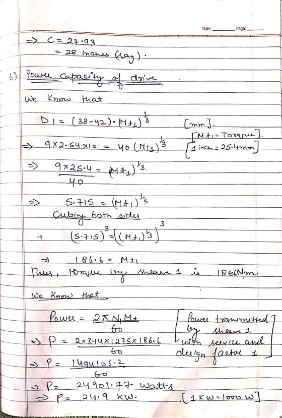
Two C180 V-Belts are used in a drive consisting of a 9 inch driving sheave rotating at 1275 rpm, and a 27 inch driven sheave.
a) Find the center-to-center distance.
b) Find the power capacity of the drive assuming a service factor of 1.0 and a design factor of 1.
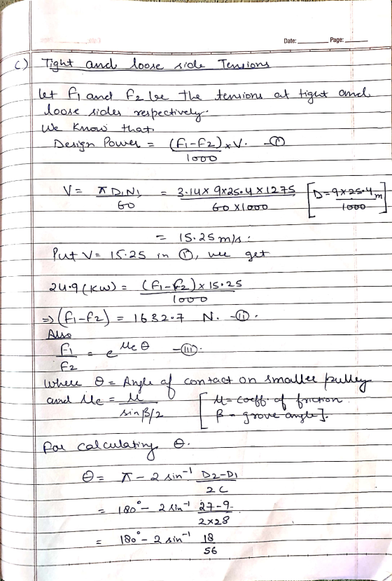
c) Find the tight and loose side tension in the belts, assuming operation at full power capacity.
d) What is the recommended preload?
Homework Answers


 .
.
![Preload is given by fp = ft- fc [ft- Tight side Tension] where fca ciray m ecente le=fi fz 3 1771.06-138.36_ z 1632.7 2 ») fp](http://img.homeworklib.com/questions/44aa2170-578c-11eb-a235-0ba2b0e6c14b.png?x-oss-process=image/resize,w_560) -
-
Add Answer to:
Two C180 V-Belts are used in a drive consisting of a 9 inch
driving sheave rotating...
2. Given a belt drive system with the following parmeters: 25 HP electrice motor, motor speed of 870 rpm, service factor of 1.3, driving sheave diameter of 13.1 inches, driven sheave diametet of...
 2. Given a belt drive system with the following parmeters: 25 HP electrice motor, motor speed of 870 rpm, service factor of 1.3, driving sheave diameter of 13.1 inches, driven sheave diametet of 27.7 inches, and a belt length of 180 inches, find the design power, the center-to-center distance for the sheaves, and the output speed. Show all work Driving Driven e2 n1 Slack side 01 D, Vb Bet speed n2 D2 Tight side Note: D1 and 02 are pitch...
Design a V-belt drive system by specify the belt size, the sheave sizes, and the number...
Design a V-belt drive system by specify the belt size, the sheave sizes, and the number of belts, the actual output speed, and the center distance. Driver type :AC motor (HT) - Driven machine :Hammer mil - Service (h/day) :10 - Input speed (rpm) :890 - Input power (hp) :25 - Nominal output speed (rpm) :310
Design the V-belt drive for the following specifications: Specify the belt size, Belt type, The sheave...
 Design the V-belt drive for the following specifications: Specify the belt size, Belt type, The sheave size, the number of belts, the angles of wrap, the belt length, The center distance, The adjusted horsepower Driver type: AC MOTOR Driven machine: Fan Service hours/day: 22 Input speed: 1750 rpm Input power: 5 hp Nominal output speed: 725 rpm
Q.9. Arubberised flat belt is moving at 14 m/s with the tension in the tight side...
 Q.9. Arubberised flat belt is moving at 14 m/s with the tension in the tight side of 10.0 kN and the slack side of 5.0 kN. The belt is 350 mm wide and 10 mm thick, and it is constructed of 5 plies of 32 oz canvas ducking. What is tension ratio in the belt? A. 2.0 В. 2.1 С. 1.9 D. 2.3 E. none of above (4 Marks) Q.10. A V-belt drive system is to be designed to transmit...
find v belt drive design power select belt type determine shive size (belt speed 4000 ft/min)...
 find v belt drive
design power
select belt type
determine shive size (belt speed 4000 ft/min)
find shive size from power rating figure
find rated power
find estimated centre distance
find belt length (by selecting standard belt length)
calculate actual centre distance
find contact angle for small shieve
determine correct factors
calculate correct power per belt
no. of belt needed
V-Belt Designing Sample Problem . Given: A 4 cylinder diesel engine runs at 80 hp, 1800 rpm, to drive a...
find v belt drive
design power
select belt type
determine shive size (belt speed 4000 ft/min)
find shive size from power rating figure
find rated power
find estimated centre distance
find belt length (by selecting standard belt length)
calculate actual centre distance
find contact angle for small shieve
determine correct factors
calculate correct power per belt
no. of belt needed
V-Belt Designing Sample Problem . Given: A 4 cylinder diesel engine runs at 80 hp, 1800 rpm, to drive a...
Figure 1 shows the layout of countershaft used to transmit power to a blower through a...
 Figure 1 shows the layout of countershaft used to transmit power to a blower through a pulley drive (4-5). Pulley (driving sheave) 4 has a diameter of 125-mm and pulley (driven sheave) 5 has a diameter of 75 mm. Pulley 5 is mounted vertically below pulley 4 (as shown in the figure). Belt tension on the loose side is 20% of the tension on the tight side. A power of 7.5 kW is transmitted via the gear set (2-3) from...
A countershaft carrying two V-belt pulleys is shown in the figure. Pulley A receives power from...
 A countershaft carrying two V-belt pulleys is shown in the
figure. Pulley A receives power from a motor through a belt with
the belt tensions shown. The power is transmitted through the shaft
and delivered to the belt on pulley B. Assume the belt tension on
the loose side at B is 15 percent of the tension on the tight side.
Yield of the Shaft ?? = 560 ???
a) Determine the tensions in the belt on pulley B, assuming...
A countershaft carrying two V-belt pulleys is shown in the
figure. Pulley A receives power from a motor through a belt with
the belt tensions shown. The power is transmitted through the shaft
and delivered to the belt on pulley B. Assume the belt tension on
the loose side at B is 15 percent of the tension on the tight side.
Yield of the Shaft ?? = 560 ???
a) Determine the tensions in the belt on pulley B, assuming...
Q.17. How much power is supplied to two meshed spur gears if the driving gear rotates...
 Q.17. How much power is supplied to two meshed spur gears if the driving gear rotates at 2000 rpm, the torque 2.00 and its efficiency is 96%? driven gear is 1.00 kNm, the speed ratio of the drive is on a A. 204 kW B. 210 kW C. 109 kW D. 105 kW E. none of above (3 Marks) Q.18. Two meshed spur gears with a 210 mm centre distance and a module of 3.00 have arc of contact of...
0.2) Figure Q.2 shows a drive system in which a 20-hp electric motor drives separate output shaft...
 Desgin
0.2) Figure Q.2 shows a drive system in which a 20-hp electric motor drives separate output shafts. Gear A is mounted on the motor shafit that has a rotational spoed or 1750 rpm clockwise. Gear A drives gear train consisting of…B,C,and D thr deliver power through the shafts on which they are mounted. All gears have a diametral pitch of Pa-8.The following data are given Power delivered by gears B, C, and D: Pa Numbers of teeth for all...
Desgin
0.2) Figure Q.2 shows a drive system in which a 20-hp electric motor drives separate output shafts. Gear A is mounted on the motor shafit that has a rotational spoed or 1750 rpm clockwise. Gear A drives gear train consisting of…B,C,and D thr deliver power through the shafts on which they are mounted. All gears have a diametral pitch of Pa-8.The following data are given Power delivered by gears B, C, and D: Pa Numbers of teeth for all...
Desgin 0.2) Figure Q.2 shows a drive system in which a 20-hp electric motor drives separate...
 Desgin
0.2) Figure Q.2 shows a drive system in which a 20-hp electric motor drives separate output shafts. Gear A is mounted on the motor shafit that has a rotational spoed or 1750 rpm clockwise. Gear A drives gear train consisting of…B,C,and D thr deliver power through the shafts on which they are mounted. All gears have a diametral pitch of Pa-8.The following data are given Power delivered by gears B, C, and D: Pa Numbers of teeth for all...
Desgin
0.2) Figure Q.2 shows a drive system in which a 20-hp electric motor drives separate output shafts. Gear A is mounted on the motor shafit that has a rotational spoed or 1750 rpm clockwise. Gear A drives gear train consisting of…B,C,and D thr deliver power through the shafts on which they are mounted. All gears have a diametral pitch of Pa-8.The following data are given Power delivered by gears B, C, and D: Pa Numbers of teeth for all...
 2. Given a belt drive system with the following parmeters: 25 HP electrice motor, motor speed of 870 rpm, service factor of 1.3, driving sheave diameter of 13.1 inches, driven sheave diametet of 27.7 inches, and a belt length of 180 inches, find the design power, the center-to-center distance for the sheaves, and the output speed. Show all work Driving Driven e2 n1 Slack side 01 D, Vb Bet speed n2 D2 Tight side Note: D1 and 02 are pitch...
 Design the V-belt drive for the following specifications: Specify the belt size, Belt type, The sheave size, the number of belts, the angles of wrap, the belt length, The center distance, The adjusted horsepower Driver type: AC MOTOR Driven machine: Fan Service hours/day: 22 Input speed: 1750 rpm Input power: 5 hp Nominal output speed: 725 rpm
 Q.9. Arubberised flat belt is moving at 14 m/s with the tension in the tight side of 10.0 kN and the slack side of 5.0 kN. The belt is 350 mm wide and 10 mm thick, and it is constructed of 5 plies of 32 oz canvas ducking. What is tension ratio in the belt? A. 2.0 В. 2.1 С. 1.9 D. 2.3 E. none of above (4 Marks) Q.10. A V-belt drive system is to be designed to transmit...
 find v belt drive
design power
select belt type
determine shive size (belt speed 4000 ft/min)
find shive size from power rating figure
find rated power
find estimated centre distance
find belt length (by selecting standard belt length)
calculate actual centre distance
find contact angle for small shieve
determine correct factors
calculate correct power per belt
no. of belt needed
V-Belt Designing Sample Problem . Given: A 4 cylinder diesel engine runs at 80 hp, 1800 rpm, to drive a...
find v belt drive
design power
select belt type
determine shive size (belt speed 4000 ft/min)
find shive size from power rating figure
find rated power
find estimated centre distance
find belt length (by selecting standard belt length)
calculate actual centre distance
find contact angle for small shieve
determine correct factors
calculate correct power per belt
no. of belt needed
V-Belt Designing Sample Problem . Given: A 4 cylinder diesel engine runs at 80 hp, 1800 rpm, to drive a...
 Figure 1 shows the layout of countershaft used to transmit power to a blower through a pulley drive (4-5). Pulley (driving sheave) 4 has a diameter of 125-mm and pulley (driven sheave) 5 has a diameter of 75 mm. Pulley 5 is mounted vertically below pulley 4 (as shown in the figure). Belt tension on the loose side is 20% of the tension on the tight side. A power of 7.5 kW is transmitted via the gear set (2-3) from...
 A countershaft carrying two V-belt pulleys is shown in the
figure. Pulley A receives power from a motor through a belt with
the belt tensions shown. The power is transmitted through the shaft
and delivered to the belt on pulley B. Assume the belt tension on
the loose side at B is 15 percent of the tension on the tight side.
Yield of the Shaft ?? = 560 ???
a) Determine the tensions in the belt on pulley B, assuming...
A countershaft carrying two V-belt pulleys is shown in the
figure. Pulley A receives power from a motor through a belt with
the belt tensions shown. The power is transmitted through the shaft
and delivered to the belt on pulley B. Assume the belt tension on
the loose side at B is 15 percent of the tension on the tight side.
Yield of the Shaft ?? = 560 ???
a) Determine the tensions in the belt on pulley B, assuming...
 Q.17. How much power is supplied to two meshed spur gears if the driving gear rotates at 2000 rpm, the torque 2.00 and its efficiency is 96%? driven gear is 1.00 kNm, the speed ratio of the drive is on a A. 204 kW B. 210 kW C. 109 kW D. 105 kW E. none of above (3 Marks) Q.18. Two meshed spur gears with a 210 mm centre distance and a module of 3.00 have arc of contact of...
 Desgin
0.2) Figure Q.2 shows a drive system in which a 20-hp electric motor drives separate output shafts. Gear A is mounted on the motor shafit that has a rotational spoed or 1750 rpm clockwise. Gear A drives gear train consisting of…B,C,and D thr deliver power through the shafts on which they are mounted. All gears have a diametral pitch of Pa-8.The following data are given Power delivered by gears B, C, and D: Pa Numbers of teeth for all...
Desgin
0.2) Figure Q.2 shows a drive system in which a 20-hp electric motor drives separate output shafts. Gear A is mounted on the motor shafit that has a rotational spoed or 1750 rpm clockwise. Gear A drives gear train consisting of…B,C,and D thr deliver power through the shafts on which they are mounted. All gears have a diametral pitch of Pa-8.The following data are given Power delivered by gears B, C, and D: Pa Numbers of teeth for all...
Most questions answered within 3 hours.
-
Where is the error in this code sequence?
String s1 = "Hello";
String s2 = "ello";...
asked 10 months ago -
Financial data for Joel de Paris, Inc., for last year
follow:
Joel de Paris, Inc.
Balance...
asked 10 months ago -
Consider this reaction:
Al2(SO4)3 (aq)+ BaCl3
(aq) Al2Cl6 (aq)- +
3BaSO4(s) . What is the...
asked 10 months ago -
Suppose that Savneet is considering increasing her
recent random sample from 20 car rentals to 40...
asked 10 months ago -
Trucks arrive at an unloading terminal at an average rate of 120
per hour.
Trucks arrive...
asked 10 months ago -
Why are methanol and ethanol completely soluble in water while
octanol is not very little soluble....
asked 10 months ago -
A facilities manager at a university reads in a research report
that the mean amount of...
asked 10 months ago -
When the CuSO4 is rehydrated by adding water to the anhydrous
compound, is this an endothermic...
asked 10 months ago -
A ray of sunlight is passing from diamond into crown glass; the
angle of incidence is...
asked 10 months ago -
A block of mass 0.249 kg is placed on top of a light, vertical
spring of...
asked 10 months ago -
how do the kidneys compensate in the presences of acidosis
a) trigger hyperventilate
b) reserve acid...
asked 10 months ago -
Question 501 pts
The rental rate of capital to the firm increases. Which of the
following...
asked 10 months ago