
Homework Answers
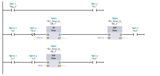
Ladder diagram solution
1)start and compare counter

2) PL1,PL2,PL3 ON and OFF
Add Answer to:
9. Consider a PLC system with the following inputs and outputs. Design a ladder diagram that...
Consider a PLC system with the following inputs and outputs. Design a ladder diagram using one an...
 Consider a PLC system with the following inputs and outputs. Design a ladder diagram using one and only one counter instruction and as many timers as you need that does the following: 9. Every time S1 is turned from off to on, it causes a counter to increment its accumulated value. . Any time that S1 stays on for 10 seconds, PL1 should light until $1 is turned back off " Any time that S1 is on, PL2 flashes on...
Develop a PLC ladder logic for motor lockout to prevent a machine operator from starting a motor that has tripped off more than 5 times in an hour. The sequence of operation is given below. Please us...
 Develop a PLC ladder logic for motor lockout to prevent a machine operator from starting a motor that has tripped off more than 5 times in an hour. The sequence of operation is given below. Please use the same names (or addresses) for input/outputs as given below. Assume the PLC tick time is 10ms 18j List of Inputs and Outputs: Sequence of Operations: Inputs: 00: Start (Momentary push button) The normally open overload (OL)-retay 01 : Stop (Momentary push button)...
THIS IS A PLC PROGRAM CALLED SIMATIC MANGER. WE NEED TO WRITE LADDER LOGIC PROGRAM AND FORM A SYM...
 THIS IS A PLC PROGRAM CALLED
SIMATIC MANGER. WE NEED TO WRITE LADDER LOGIC PROGRAM AND FORM A
SYMBOL TABLE
We were unable to transcribe this imageThe painting turn-table system shown in the following figure has a DC motor, two limit switches, a pneumatic cylinder, a start button and two spray guns. The paint guns are activated by 24 V DC voltage. The motor turns the table only in one direction Red Spray gun Blue spray gun Limit switch trigger...
THIS IS A PLC PROGRAM CALLED
SIMATIC MANGER. WE NEED TO WRITE LADDER LOGIC PROGRAM AND FORM A
SYMBOL TABLE
We were unable to transcribe this imageThe painting turn-table system shown in the following figure has a DC motor, two limit switches, a pneumatic cylinder, a start button and two spray guns. The paint guns are activated by 24 V DC voltage. The motor turns the table only in one direction Red Spray gun Blue spray gun Limit switch trigger...
 Consider a PLC system with the following inputs and outputs. Design a ladder diagram using one and only one counter instruction and as many timers as you need that does the following: 9. Every time S1 is turned from off to on, it causes a counter to increment its accumulated value. . Any time that S1 stays on for 10 seconds, PL1 should light until $1 is turned back off " Any time that S1 is on, PL2 flashes on...
 Develop a PLC ladder logic for motor lockout to prevent a machine operator from starting a motor that has tripped off more than 5 times in an hour. The sequence of operation is given below. Please use the same names (or addresses) for input/outputs as given below. Assume the PLC tick time is 10ms 18j List of Inputs and Outputs: Sequence of Operations: Inputs: 00: Start (Momentary push button) The normally open overload (OL)-retay 01 : Stop (Momentary push button)...
 THIS IS A PLC PROGRAM CALLED
SIMATIC MANGER. WE NEED TO WRITE LADDER LOGIC PROGRAM AND FORM A
SYMBOL TABLE
We were unable to transcribe this imageThe painting turn-table system shown in the following figure has a DC motor, two limit switches, a pneumatic cylinder, a start button and two spray guns. The paint guns are activated by 24 V DC voltage. The motor turns the table only in one direction Red Spray gun Blue spray gun Limit switch trigger...
THIS IS A PLC PROGRAM CALLED
SIMATIC MANGER. WE NEED TO WRITE LADDER LOGIC PROGRAM AND FORM A
SYMBOL TABLE
We were unable to transcribe this imageThe painting turn-table system shown in the following figure has a DC motor, two limit switches, a pneumatic cylinder, a start button and two spray guns. The paint guns are activated by 24 V DC voltage. The motor turns the table only in one direction Red Spray gun Blue spray gun Limit switch trigger...
Most questions answered within 3 hours.
-
Where is the error in this code sequence?
String s1 = "Hello";
String s2 = "ello";...
asked 10 months ago -
Financial data for Joel de Paris, Inc., for last year
follow:
Joel de Paris, Inc.
Balance...
asked 10 months ago -
Consider this reaction:
Al2(SO4)3 (aq)+ BaCl3
(aq) Al2Cl6 (aq)- +
3BaSO4(s) . What is the...
asked 10 months ago -
Suppose that Savneet is considering increasing her
recent random sample from 20 car rentals to 40...
asked 10 months ago -
Trucks arrive at an unloading terminal at an average rate of 120
per hour.
Trucks arrive...
asked 10 months ago -
Why are methanol and ethanol completely soluble in water while
octanol is not very little soluble....
asked 10 months ago -
A facilities manager at a university reads in a research report
that the mean amount of...
asked 10 months ago -
When the CuSO4 is rehydrated by adding water to the anhydrous
compound, is this an endothermic...
asked 10 months ago -
A ray of sunlight is passing from diamond into crown glass; the
angle of incidence is...
asked 10 months ago -
A block of mass 0.249 kg is placed on top of a light, vertical
spring of...
asked 10 months ago -
how do the kidneys compensate in the presences of acidosis
a) trigger hyperventilate
b) reserve acid...
asked 10 months ago -
Question 501 pts
The rental rate of capital to the firm increases. Which of the
following...
asked 10 months ago