
Homework Answers


Add Answer to:
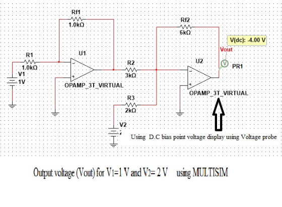
it would be awesome if you could solve this step by step. use
of multisim is...
MENG 207-ELECTRICITY Department of Engineering & Design at Eastern Washington University Lab 6 PRE LAB 1. Print out lab handout and bring to lalb 2. Do calculations for part 1 in RC CIRCUIT s...
 MENG 207-ELECTRICITY Department of Engineering & Design at Eastern Washington University Lab 6 PRE LAB 1. Print out lab handout and bring to lalb 2. Do calculations for part 1 in RC CIRCUIT section. 3. Do calculations for part 1 in RL CIRCUIT section. 4. Do calculations for part 1 in RLC CIRCUIT section OBECTVE:response Use Multisim to study the transient response of an RC and RL circuit, and the frequency response of an RLC circuit. PROCEDURES 1. Record every...
It would be greatly appreciated if you could provide step by step solutions for the problems...
 It would be greatly appreciated if you could provide step by
step solutions for the problems below.
Phasors and complex impedance 1. A resistor R and capacitor C are connected in series with an AC voltage source with frequency fand maximum voltage Vo. a. Find the complex impedance (in the form Z -R+jx). If the impedance is written in polar form (z - Zel*), find expressions for Z and gi Write your answers in terms of the variables R, C,...
It would be greatly appreciated if you could provide step by
step solutions for the problems below.
Phasors and complex impedance 1. A resistor R and capacitor C are connected in series with an AC voltage source with frequency fand maximum voltage Vo. a. Find the complex impedance (in the form Z -R+jx). If the impedance is written in polar form (z - Zel*), find expressions for Z and gi Write your answers in terms of the variables R, C,...
Could you please show me how I can drw those circuits. please using (NI Multisim 14)...
 Could you please show me how I can drw those circuits.
please using (NI Multisim 14)
Optocoupler Objectives Use an ohmmeter to determine the condition of the optoisolator. Observe the operation of an optocoupler. Determine the maximum frequency response of the optocoupler. Required Materials (1) Dual DC power supply (1) Function generator (1) Oscilloscope (2) Multimeters (1) Optocoupler (ECG3040) (1) 3.9ΚΩ resistor (1) 220 resistor Introduction An optoisolator is a hybrid integrated circuit that contains an LED on one side...
Could you please show me how I can drw those circuits.
please using (NI Multisim 14)
Optocoupler Objectives Use an ohmmeter to determine the condition of the optoisolator. Observe the operation of an optocoupler. Determine the maximum frequency response of the optocoupler. Required Materials (1) Dual DC power supply (1) Function generator (1) Oscilloscope (2) Multimeters (1) Optocoupler (ECG3040) (1) 3.9ΚΩ resistor (1) 220 resistor Introduction An optoisolator is a hybrid integrated circuit that contains an LED on one side...
If you could provide a step by step on how to solve this problem, I would...
If you could provide a step by step on how to solve this problem, I would greatly appreciate it...thanks! The concentration of iodide ions in a saturated solution of lead (II) iodide is _____M. The solubility product constant of PbI2 is 1.4x10⁻⁸.
For the following circuit: (a) Second step use Mesh-Current Method to solve for all of the...
 For the following circuit: (a) Second step use Mesh-Current Method to solve for all of the currents flowing in each of the different resistors in the circuit. Show all steps. (b) Find the current flowing from the voltage source and the voltage across the current source. (c) Calculate what i, and v, are in the circuit. i 45 Ω 2 A 60 12 512 V 10 V 2012 3512 1012 +
How would I calculate the readings for amps and voltage to compare to the voltmeter readings. ...
 How would I calculate the readings for amps and voltage to
compare to the voltmeter readings.
Circuit-Lab-U12 (2) - Multisim - ICircuit-Lab-U12 (2) Eile Edit View Place MCU Simulate Transfer Iools Beports Options Window Help 9 -- In-Use List II Interactive Multimeter-XMM3 3 Multimeler-XMM1 11 24 A XMM1 XMM3 - . A y dB A V dB I 1 R1 R2 XMM4 Set. 10mH Set... Multimeter-XMM4 212 300 A V1 C2 3.47HF) A v Q dB C1 1.6kVrms 636HZ 60...
How would I calculate the readings for amps and voltage to
compare to the voltmeter readings.
Circuit-Lab-U12 (2) - Multisim - ICircuit-Lab-U12 (2) Eile Edit View Place MCU Simulate Transfer Iools Beports Options Window Help 9 -- In-Use List II Interactive Multimeter-XMM3 3 Multimeler-XMM1 11 24 A XMM1 XMM3 - . A y dB A V dB I 1 R1 R2 XMM4 Set. 10mH Set... Multimeter-XMM4 212 300 A V1 C2 3.47HF) A v Q dB C1 1.6kVrms 636HZ 60...
Can you use Multisim or something similar. I got the truth table and design, but having...
 Can you use Multisim or something similar. I got the truth table
and design, but having a hard time with the actual wiring.
I need to see where each cable and light bulb go.
3.4. Multiplexer Multiplexers are very useful components in digital systems. They transfer a large number of information units over a smaller number of channels, (usually one channel) under the control of selection signals. Fig. 3 is a 4-line to l-line MUX. In this circuit, lo, 11, 12,...
Can you use Multisim or something similar. I got the truth table
and design, but having a hard time with the actual wiring.
I need to see where each cable and light bulb go.
3.4. Multiplexer Multiplexers are very useful components in digital systems. They transfer a large number of information units over a smaller number of channels, (usually one channel) under the control of selection signals. Fig. 3 is a 4-line to l-line MUX. In this circuit, lo, 11, 12,...
Hello, could you please solve it step by step. Thank you! define jauch that j*=-1 6....
 Hello, could you please solve it step by step. Thank you!
define jauch that j*=-1 6. For queation 6 we (a) Let z 2 5j and w = 5+j4. Determine the following [2 marka 3 marks 111 6 marka (b) Let z 1+3j. z in exponential form (i Expreaa [2 marka (ii) Find z5 in rectangular form a + jb [3 marka Find all the roote of Vz 111 [4 marks
Hello, could you please solve it step by step. Thank you!
define jauch that j*=-1 6. For queation 6 we (a) Let z 2 5j and w = 5+j4. Determine the following [2 marka 3 marks 111 6 marka (b) Let z 1+3j. z in exponential form (i Expreaa [2 marka (ii) Find z5 in rectangular form a + jb [3 marka Find all the roote of Vz 111 [4 marks
Hello, could you solve these problems? I hope no mistakes. 1. Find all the currents and...
 Hello, could you solve these problems? I hope no mistakes.
1. Find all the currents and voltages in the following circuit. For what values of V(collector voltage of Q2) is I =IREF valid? +6V TREF 32 KN OV -6 V 2. The following circuit shows a common-emitter amplifier with emitter resistances. Vec RCP Vis SR, RE, Rę, = = a) Draw the equivalent small-signal T-model for the circuit. b) Derive an expressions for Rin and Gy= Vo/Vsig (No need for...
Hello, could you solve these problems? I hope no mistakes.
1. Find all the currents and voltages in the following circuit. For what values of V(collector voltage of Q2) is I =IREF valid? +6V TREF 32 KN OV -6 V 2. The following circuit shows a common-emitter amplifier with emitter resistances. Vec RCP Vis SR, RE, Rę, = = a) Draw the equivalent small-signal T-model for the circuit. b) Derive an expressions for Rin and Gy= Vo/Vsig (No need for...
please use multisim to answer all the parts. EXPERIMENT 3 TESTING SERIES & PARALLEL RESONANCES Objectives:...
 please use multisim to answer all the parts.
EXPERIMENT 3 TESTING SERIES & PARALLEL RESONANCES Objectives: To examine the conditions of resonances To observe the resonant circuit properties Equipment & components: A personal computer with Multisim software Preview questions: 1. How does the resonant frequency relate to the inductance and capacitance in a series LC circuit? 2. When the circuit in Figure 1 is tuned to resonant frequency, how does the voltage cross the resistor relate to the applied voltage?...
please use multisim to answer all the parts.
EXPERIMENT 3 TESTING SERIES & PARALLEL RESONANCES Objectives: To examine the conditions of resonances To observe the resonant circuit properties Equipment & components: A personal computer with Multisim software Preview questions: 1. How does the resonant frequency relate to the inductance and capacitance in a series LC circuit? 2. When the circuit in Figure 1 is tuned to resonant frequency, how does the voltage cross the resistor relate to the applied voltage?...
 MENG 207-ELECTRICITY Department of Engineering & Design at Eastern Washington University Lab 6 PRE LAB 1. Print out lab handout and bring to lalb 2. Do calculations for part 1 in RC CIRCUIT section. 3. Do calculations for part 1 in RL CIRCUIT section. 4. Do calculations for part 1 in RLC CIRCUIT section OBECTVE:response Use Multisim to study the transient response of an RC and RL circuit, and the frequency response of an RLC circuit. PROCEDURES 1. Record every...
 It would be greatly appreciated if you could provide step by
step solutions for the problems below.
Phasors and complex impedance 1. A resistor R and capacitor C are connected in series with an AC voltage source with frequency fand maximum voltage Vo. a. Find the complex impedance (in the form Z -R+jx). If the impedance is written in polar form (z - Zel*), find expressions for Z and gi Write your answers in terms of the variables R, C,...
It would be greatly appreciated if you could provide step by
step solutions for the problems below.
Phasors and complex impedance 1. A resistor R and capacitor C are connected in series with an AC voltage source with frequency fand maximum voltage Vo. a. Find the complex impedance (in the form Z -R+jx). If the impedance is written in polar form (z - Zel*), find expressions for Z and gi Write your answers in terms of the variables R, C,...
 Could you please show me how I can drw those circuits.
please using (NI Multisim 14)
Optocoupler Objectives Use an ohmmeter to determine the condition of the optoisolator. Observe the operation of an optocoupler. Determine the maximum frequency response of the optocoupler. Required Materials (1) Dual DC power supply (1) Function generator (1) Oscilloscope (2) Multimeters (1) Optocoupler (ECG3040) (1) 3.9ΚΩ resistor (1) 220 resistor Introduction An optoisolator is a hybrid integrated circuit that contains an LED on one side...
Could you please show me how I can drw those circuits.
please using (NI Multisim 14)
Optocoupler Objectives Use an ohmmeter to determine the condition of the optoisolator. Observe the operation of an optocoupler. Determine the maximum frequency response of the optocoupler. Required Materials (1) Dual DC power supply (1) Function generator (1) Oscilloscope (2) Multimeters (1) Optocoupler (ECG3040) (1) 3.9ΚΩ resistor (1) 220 resistor Introduction An optoisolator is a hybrid integrated circuit that contains an LED on one side...
 For the following circuit: (a) Second step use Mesh-Current Method to solve for all of the currents flowing in each of the different resistors in the circuit. Show all steps. (b) Find the current flowing from the voltage source and the voltage across the current source. (c) Calculate what i, and v, are in the circuit. i 45 Ω 2 A 60 12 512 V 10 V 2012 3512 1012 +
 How would I calculate the readings for amps and voltage to
compare to the voltmeter readings.
Circuit-Lab-U12 (2) - Multisim - ICircuit-Lab-U12 (2) Eile Edit View Place MCU Simulate Transfer Iools Beports Options Window Help 9 -- In-Use List II Interactive Multimeter-XMM3 3 Multimeler-XMM1 11 24 A XMM1 XMM3 - . A y dB A V dB I 1 R1 R2 XMM4 Set. 10mH Set... Multimeter-XMM4 212 300 A V1 C2 3.47HF) A v Q dB C1 1.6kVrms 636HZ 60...
How would I calculate the readings for amps and voltage to
compare to the voltmeter readings.
Circuit-Lab-U12 (2) - Multisim - ICircuit-Lab-U12 (2) Eile Edit View Place MCU Simulate Transfer Iools Beports Options Window Help 9 -- In-Use List II Interactive Multimeter-XMM3 3 Multimeler-XMM1 11 24 A XMM1 XMM3 - . A y dB A V dB I 1 R1 R2 XMM4 Set. 10mH Set... Multimeter-XMM4 212 300 A V1 C2 3.47HF) A v Q dB C1 1.6kVrms 636HZ 60...
 Can you use Multisim or something similar. I got the truth table
and design, but having a hard time with the actual wiring.
I need to see where each cable and light bulb go.
3.4. Multiplexer Multiplexers are very useful components in digital systems. They transfer a large number of information units over a smaller number of channels, (usually one channel) under the control of selection signals. Fig. 3 is a 4-line to l-line MUX. In this circuit, lo, 11, 12,...
Can you use Multisim or something similar. I got the truth table
and design, but having a hard time with the actual wiring.
I need to see where each cable and light bulb go.
3.4. Multiplexer Multiplexers are very useful components in digital systems. They transfer a large number of information units over a smaller number of channels, (usually one channel) under the control of selection signals. Fig. 3 is a 4-line to l-line MUX. In this circuit, lo, 11, 12,...
 Hello, could you please solve it step by step. Thank you!
define jauch that j*=-1 6. For queation 6 we (a) Let z 2 5j and w = 5+j4. Determine the following [2 marka 3 marks 111 6 marka (b) Let z 1+3j. z in exponential form (i Expreaa [2 marka (ii) Find z5 in rectangular form a + jb [3 marka Find all the roote of Vz 111 [4 marks
Hello, could you please solve it step by step. Thank you!
define jauch that j*=-1 6. For queation 6 we (a) Let z 2 5j and w = 5+j4. Determine the following [2 marka 3 marks 111 6 marka (b) Let z 1+3j. z in exponential form (i Expreaa [2 marka (ii) Find z5 in rectangular form a + jb [3 marka Find all the roote of Vz 111 [4 marks
 Hello, could you solve these problems? I hope no mistakes.
1. Find all the currents and voltages in the following circuit. For what values of V(collector voltage of Q2) is I =IREF valid? +6V TREF 32 KN OV -6 V 2. The following circuit shows a common-emitter amplifier with emitter resistances. Vec RCP Vis SR, RE, Rę, = = a) Draw the equivalent small-signal T-model for the circuit. b) Derive an expressions for Rin and Gy= Vo/Vsig (No need for...
Hello, could you solve these problems? I hope no mistakes.
1. Find all the currents and voltages in the following circuit. For what values of V(collector voltage of Q2) is I =IREF valid? +6V TREF 32 KN OV -6 V 2. The following circuit shows a common-emitter amplifier with emitter resistances. Vec RCP Vis SR, RE, Rę, = = a) Draw the equivalent small-signal T-model for the circuit. b) Derive an expressions for Rin and Gy= Vo/Vsig (No need for...
 please use multisim to answer all the parts.
EXPERIMENT 3 TESTING SERIES & PARALLEL RESONANCES Objectives: To examine the conditions of resonances To observe the resonant circuit properties Equipment & components: A personal computer with Multisim software Preview questions: 1. How does the resonant frequency relate to the inductance and capacitance in a series LC circuit? 2. When the circuit in Figure 1 is tuned to resonant frequency, how does the voltage cross the resistor relate to the applied voltage?...
please use multisim to answer all the parts.
EXPERIMENT 3 TESTING SERIES & PARALLEL RESONANCES Objectives: To examine the conditions of resonances To observe the resonant circuit properties Equipment & components: A personal computer with Multisim software Preview questions: 1. How does the resonant frequency relate to the inductance and capacitance in a series LC circuit? 2. When the circuit in Figure 1 is tuned to resonant frequency, how does the voltage cross the resistor relate to the applied voltage?...
Most questions answered within 3 hours.
-
Where is the error in this code sequence?
String s1 = "Hello";
String s2 = "ello";...
asked 10 months ago -
Financial data for Joel de Paris, Inc., for last year
follow:
Joel de Paris, Inc.
Balance...
asked 10 months ago -
Consider this reaction:
Al2(SO4)3 (aq)+ BaCl3
(aq) Al2Cl6 (aq)- +
3BaSO4(s) . What is the...
asked 10 months ago -
Suppose that Savneet is considering increasing her
recent random sample from 20 car rentals to 40...
asked 10 months ago -
Trucks arrive at an unloading terminal at an average rate of 120
per hour.
Trucks arrive...
asked 10 months ago -
Why are methanol and ethanol completely soluble in water while
octanol is not very little soluble....
asked 10 months ago -
A facilities manager at a university reads in a research report
that the mean amount of...
asked 10 months ago -
When the CuSO4 is rehydrated by adding water to the anhydrous
compound, is this an endothermic...
asked 10 months ago -
A ray of sunlight is passing from diamond into crown glass; the
angle of incidence is...
asked 10 months ago -
A block of mass 0.249 kg is placed on top of a light, vertical
spring of...
asked 10 months ago -
how do the kidneys compensate in the presences of acidosis
a) trigger hyperventilate
b) reserve acid...
asked 10 months ago -
Question 501 pts
The rental rate of capital to the firm increases. Which of the
following...
asked 10 months ago