

Homework Answers


Add Answer to:
show step by step soultion please
23. For the circuit shown in Figure P5.23, let v(0)...
Circuit Analysis in the s-Domain 15.3. The initial voltage across the capacitor in the circuit shown in Figure P15.3 is v(0) 1 V, and the initial current through the inductor is i(0)0 mA Find th...
 Circuit Analysis in the s-Domain 15.3. The initial voltage across the capacitor in the circuit shown in Figure P15.3 is v(0) 1 V, and the initial current through the inductor is i(0)0 mA Find the voltage vo (t) across the capacitor for t 2 0 Figure P15.3 50 mH 1 kS2 V. Volt) T 0.1 μF The circuit in the s-domain is shown below. R2 Va 1k 0.05s 1/(sC)-1e7/s Vo R1 2k V (0-ys 5/s 1/s 1 format long; 2...
Q6: In the circuit shown in Figure-6, assume the initial conditions, i0-0 and v(0)-0.The input, Vin...
 Q6: In the circuit shown in Figure-6, assume the initial conditions, i0-0 and v(0)-0.The input, Vin is a step voltage of 5V at t20. (i Draw the Laplace Transformed circuit of the network at t20. (i Find Laplace function, Vou s). (iii) Solve for Vourt) [61 2? 4? Vin-5u(t) 0.2F 0.5H v out Figure-6 4
2. In the circuit shown in Figure 2, let C=0.5 F L=1H, R-312. Find the voltage vo(t) for t>0 L volt) Figure 2 2. In the circuit shown in Figure 2, let C=0.5 F L=1H, R-312. Find the voltage vo...
 2. In the circuit shown in Figure 2, let C=0.5 F L=1H, R-312. Find the voltage vo(t) for t>0 L volt) Figure 2
2. In the circuit shown in Figure 2, let C=0.5 F L=1H, R-312. Find the voltage vo(t) for t>0 L volt) Figure 2
2. In the circuit shown in Figure 2, let C=0.5 F L=1H, R-312. Find the voltage vo(t) for t>0 L volt) Figure 2
23. The A-1 characteristic of a magnetic circuit, as shown in Figure P3-23, consists of two...
 23. The A-1 characteristic of a magnetic circuit, as shown in Figure P3-23, consists of two straight line segments. Compute the energy Wn and coenergy W for the magnetic circuit at point a and at point b. λ (weber-turns) 2.0 i (amperes) 4 Figure P3-23
3 Draw the circuit at too and force i(0*) and ve(0*). Then solve for v(0*) and...
 3 Draw the circuit at too and force i(0*) and ve(0*). Then solve for v(0*) and 4c(O*). Find the second intial condition given as 2 (7) 3- Draw the circuit at tm Replace the inductor with short circuit, and the capecitor with open circuit Then sove for 4i (o) and v (oo). Once the three values are obtained, you have two initial conditions to solve for A and B. In this lab, you will build a parallel RLC circuit shown...
Function Generatr Inductor Model Ra R, Figure 1 Series RLC Circuit Preliminary This laboratory wi...
 Function Generatr Inductor Model Ra R, Figure 1 Series RLC Circuit Preliminary This laboratory will demonstrate how varying resistance changes the natural response of a series RLC circuit (Fig. 1). The function generator is modeled as an ideal voltage source v(t) 5 u() V in series with source resistance Rs-50Q. After measurements using an LCR meter, the inductor is modeled as an ideal L 90 mH inductor in series with resistance RL-20Q. The capacitance is C-0.22 μF. 1) Calculate the...
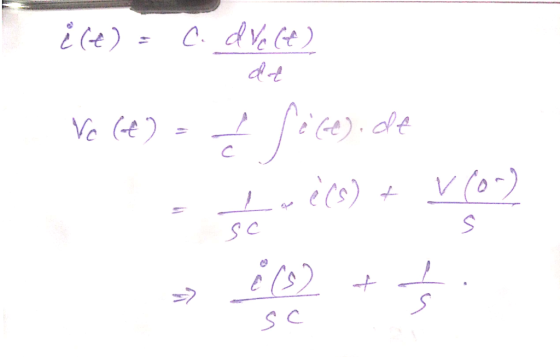
1. Given i(t) Cut) Figure 2.1: Step voltage applied to a series RLC circuit. (a) Verify...
 1. Given i(t) Cut) Figure 2.1: Step voltage applied to a series RLC circuit. (a) Verify that the differential equation for v(t) is found as dt2 L dt LC LC (b) If v(0)-5 V and i(0)-OA. find the voltage response, u(t), for t >0 when v, 5V, R#330 n, L-100 mil, C., 0.1uF (c) Now suppose we replace the 5 V source in our circuit with a squarewave as shown below: w(t) Figure 2.2 From the response of v(t) that...
please show step by step . The circuit shown in Fig. 6 is switched on at...
 please show step by step
. The circuit shown in Fig. 6 is switched on at time t-0. How long does it take for the capacitor to attain 70% of its final value? Assume the initial voltage across the capacitor to be zero. Also find the time constant of the circuit after the switch is closed. R,-100Ω 200Ω 0.01F Fig. 6
please show step by step
. The circuit shown in Fig. 6 is switched on at time t-0. How long does it take for the capacitor to attain 70% of its final value? Assume the initial voltage across the capacitor to be zero. Also find the time constant of the circuit after the switch is closed. R,-100Ω 200Ω 0.01F Fig. 6
For the circuit shown, find the following: a) v(0+), the voltage across the capacitor right after...
 For the circuit shown, find the following: a) v(0+), the voltage across the capacitor right after the switch closes. b) v), the voltage across the capacitor after the switch has been closed for a long time. c) v(T), the voltage across the capacitor after one time constant. 2. 3 S2 I(t) 12 V+ 6 Ω 0.5 F u(t) 3. For the circuit above, write the differential equation for t > 0.
c) For the circuit shown in Figure 3, where u(t) is the unit step function, using...
 c) For the circuit shown in Figure 3, where u(t) is the unit step function, using Laplace transform methods and showing all working, find the response i(t) fort> 0. (9 marks) 4H 7e-u(t) v(1) 352 322 Figure 3
 Circuit Analysis in the s-Domain 15.3. The initial voltage across the capacitor in the circuit shown in Figure P15.3 is v(0) 1 V, and the initial current through the inductor is i(0)0 mA Find the voltage vo (t) across the capacitor for t 2 0 Figure P15.3 50 mH 1 kS2 V. Volt) T 0.1 μF The circuit in the s-domain is shown below. R2 Va 1k 0.05s 1/(sC)-1e7/s Vo R1 2k V (0-ys 5/s 1/s 1 format long; 2...
 Q6: In the circuit shown in Figure-6, assume the initial conditions, i0-0 and v(0)-0.The input, Vin is a step voltage of 5V at t20. (i Draw the Laplace Transformed circuit of the network at t20. (i Find Laplace function, Vou s). (iii) Solve for Vourt) [61 2? 4? Vin-5u(t) 0.2F 0.5H v out Figure-6 4
 2. In the circuit shown in Figure 2, let C=0.5 F L=1H, R-312. Find the voltage vo(t) for t>0 L volt) Figure 2
2. In the circuit shown in Figure 2, let C=0.5 F L=1H, R-312. Find the voltage vo(t) for t>0 L volt) Figure 2
2. In the circuit shown in Figure 2, let C=0.5 F L=1H, R-312. Find the voltage vo(t) for t>0 L volt) Figure 2
 23. The A-1 characteristic of a magnetic circuit, as shown in Figure P3-23, consists of two straight line segments. Compute the energy Wn and coenergy W for the magnetic circuit at point a and at point b. λ (weber-turns) 2.0 i (amperes) 4 Figure P3-23
 3 Draw the circuit at too and force i(0*) and ve(0*). Then solve for v(0*) and 4c(O*). Find the second intial condition given as 2 (7) 3- Draw the circuit at tm Replace the inductor with short circuit, and the capecitor with open circuit Then sove for 4i (o) and v (oo). Once the three values are obtained, you have two initial conditions to solve for A and B. In this lab, you will build a parallel RLC circuit shown...
 Function Generatr Inductor Model Ra R, Figure 1 Series RLC Circuit Preliminary This laboratory will demonstrate how varying resistance changes the natural response of a series RLC circuit (Fig. 1). The function generator is modeled as an ideal voltage source v(t) 5 u() V in series with source resistance Rs-50Q. After measurements using an LCR meter, the inductor is modeled as an ideal L 90 mH inductor in series with resistance RL-20Q. The capacitance is C-0.22 μF. 1) Calculate the...
 1. Given i(t) Cut) Figure 2.1: Step voltage applied to a series RLC circuit. (a) Verify that the differential equation for v(t) is found as dt2 L dt LC LC (b) If v(0)-5 V and i(0)-OA. find the voltage response, u(t), for t >0 when v, 5V, R#330 n, L-100 mil, C., 0.1uF (c) Now suppose we replace the 5 V source in our circuit with a squarewave as shown below: w(t) Figure 2.2 From the response of v(t) that...
 please show step by step
. The circuit shown in Fig. 6 is switched on at time t-0. How long does it take for the capacitor to attain 70% of its final value? Assume the initial voltage across the capacitor to be zero. Also find the time constant of the circuit after the switch is closed. R,-100Ω 200Ω 0.01F Fig. 6
please show step by step
. The circuit shown in Fig. 6 is switched on at time t-0. How long does it take for the capacitor to attain 70% of its final value? Assume the initial voltage across the capacitor to be zero. Also find the time constant of the circuit after the switch is closed. R,-100Ω 200Ω 0.01F Fig. 6
 For the circuit shown, find the following: a) v(0+), the voltage across the capacitor right after the switch closes. b) v), the voltage across the capacitor after the switch has been closed for a long time. c) v(T), the voltage across the capacitor after one time constant. 2. 3 S2 I(t) 12 V+ 6 Ω 0.5 F u(t) 3. For the circuit above, write the differential equation for t > 0.
 c) For the circuit shown in Figure 3, where u(t) is the unit step function, using Laplace transform methods and showing all working, find the response i(t) fort> 0. (9 marks) 4H 7e-u(t) v(1) 352 322 Figure 3
Most questions answered within 3 hours.
-
Where is the error in this code sequence?
String s1 = "Hello";
String s2 = "ello";...
asked 11 months ago -
Financial data for Joel de Paris, Inc., for last year
follow:
Joel de Paris, Inc.
Balance...
asked 11 months ago -
Consider this reaction:
Al2(SO4)3 (aq)+ BaCl3
(aq) Al2Cl6 (aq)- +
3BaSO4(s) . What is the...
asked 11 months ago -
Suppose that Savneet is considering increasing her
recent random sample from 20 car rentals to 40...
asked 11 months ago -
Trucks arrive at an unloading terminal at an average rate of 120
per hour.
Trucks arrive...
asked 11 months ago -
Why are methanol and ethanol completely soluble in water while
octanol is not very little soluble....
asked 11 months ago -
A facilities manager at a university reads in a research report
that the mean amount of...
asked 11 months ago -
When the CuSO4 is rehydrated by adding water to the anhydrous
compound, is this an endothermic...
asked 11 months ago -
A ray of sunlight is passing from diamond into crown glass; the
angle of incidence is...
asked 11 months ago -
A block of mass 0.249 kg is placed on top of a light, vertical
spring of...
asked 11 months ago -
how do the kidneys compensate in the presences of acidosis
a) trigger hyperventilate
b) reserve acid...
asked 11 months ago -
Question 501 pts
The rental rate of capital to the firm increases. Which of the
following...
asked 11 months ago