
Homework Answers
Add Answer to:
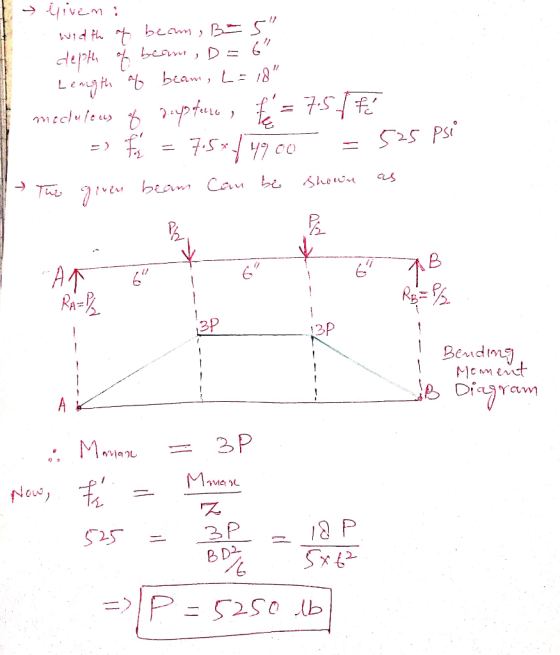
Problem 1 {12} Consider the test arrangement shown in the figure below. In this arrangement, a...
A 15-ft solid concrete cantilever beam with a rectangular cross-section is shown below. It supports a...
 A 15-ft solid concrete cantilever beam with a rectangular cross-section is shown below. It supports a load w = 2,150 lb/ft. The concrete has a tensile strength of 650 psi and a compressive strength of 6,000 psi. (a) Determine the maximum tensile and compressive stresses in the beam due to the applied load (b) Explain where failure would initiate in the solid concrete beam under the applied load. (c) Because the solid concrete beam is not adequate to carry the...
Based on tributary load analysis, the dead and live loads, wd and wų, respectively, acting on...
 Based on tributary load analysis, the dead and live loads, wd and wų, respectively, acting on a beam in a vertical load resisting system are shown below. The concrete is normalweight with compressive strength f=5000 psi. Note that the given dead load includes the self-weight of the beam and slab. Section wp=1.2 kip/ft, wu=1.5 kip/ft be-45 inch 5 inch 1 30 inch B A 10 inch In=10 ft 1. Design and detail the beam for positive flexure at section A....
Reinforced concrete Problem #1 (40 points): A beam with x-section shown in the figure is made...
 Reinforced concrete
Problem #1 (40 points): A beam with x-section shown in the figure is made out of concrete with compressive strength fc = 4000 psi and the steel reinfrocemnt is of Grade 60 (fy 60000psi). Determine 1 The maximum compressive stress in the concrete f and the tensils stress in the steel , if the section is subjected to a bending moment of 130 ft-k (assume n 8) N.A._ 23" 23-х 4 #10 (5.06 in. 3" 18"
Reinforced concrete
Problem #1 (40 points): A beam with x-section shown in the figure is made out of concrete with compressive strength fc = 4000 psi and the steel reinfrocemnt is of Grade 60 (fy 60000psi). Determine 1 The maximum compressive stress in the concrete f and the tensils stress in the steel , if the section is subjected to a bending moment of 130 ft-k (assume n 8) N.A._ 23" 23-х 4 #10 (5.06 in. 3" 18"
Qu estion 1: (25 points) The beam shown below has a span of 13 ft and is reinforced with bars tha...
 Qu estion 1: (25 points) The beam shown below has a span of 13 ft and is reinforced with bars that ext end 8 inch beyond the face of the support. The centerline of the longitudinal bars nearest the side ace (i.e., the "outside bars") is 3.5 inch from, the side face as shown below. The concrete has a compressive strength of 3.0 ksi, and the reinforcement is Grade 60. The beam is loaded with a distributed live load (w)...
The point loads are placed at the fixed positions shown in the figure and they are...
 The point loads are placed at the fixed positions shown in the figure and they are live loads. E C (centre) f = 32 Mpa fer= 3 MPa fsv = 500 MPa E = 200 GPa E = 28600 MPa a Cross section The following values are used for the question. . l = 3 m load before cracking • 12 = 2.5 m . P = 2 KN . a = 50 mm . G-5 kN/m • b =...
Cracking Moment (Uncracked Concrete Stage) Problem 1) Problem 2.6 (page 55, McCormac and Brown, gth Ed.)...
 Cracking Moment (Uncracked Concrete Stage) Problem 1) Problem 2.6 (page 55, McCormac and Brown, gth Ed.) Note: Modify the total depth of the beam from 24" to 26" and the depth of the steel rebars from 21" to 23". Transformed Area Method (Concrete Cracked- Elastic Stresses Stage) Problem 2) Problem 2.13 (page 56, McCormac and Brown, 8th Ed.) Note: Make the following changes: Change fe to 5 ksi use the values and dimensions shown in the figure below 1) 2)...
4. (a) Design a bolted joint to join the two members shown in the figure below. Specify the number of bolts, the pattern, the bolt grade, and the bolt size 8 x4 x 12 Box sect 4 in 6in 0.50 in ty...
 4. (a) Design a bolted joint to join the two members shown in the figure below. Specify the number of bolts, the pattern, the bolt grade, and the bolt size 8 x4 x 12 Box sect 4 in 6in 0.50 in typical 0.50 plate 12 000 lb P (b). Two steel plates are joined using 3/8-inch parallel-loaded fillet welds. The yield strength, Sy, and the length of the welds are known. The design factor is 3.5. Determine the maximum tensile...
simply supported reinforced concrete beam of rectangular section is hung on the left end by a 400mm square post working in tension, as shown in the figure below. The beam supports a uniform dead l...
 simply supported reinforced concrete beam of rectangular section is hung on the left end by a 400mm square post working in tension, as shown in the figure below. The beam supports a uniform dead load (DL) gf 100 KN/m (excluding its own weight) and upiform live load LL) of 40KN/m. The beam is reinforced with 025 longitudinal rebars with 40mm cleat cover to the stirrups. Material properties: fy 420 MPa, fe 25 MPa. Beam dimension b 400mm and h 600mm....
Problem-1 (15 points) A cantilever beam ACB supports a concentrated load P and a couple moment Mo, as shown in the figure below. (a) Determine the total strain energy of the beam, (b) Determine t...
 Problem-1 (15 points) A cantilever beam ACB supports a concentrated load P and a couple moment Mo, as shown in the figure below. (a) Determine the total strain energy of the beam, (b) Determine the deflections δ and δ8 at points C and B respectively. (c) Determine the angle of rotations 0 and θι, at points C and B respectively. Use the Castigliano's theorem(s). Assume that the beam's flexural rigidity is EI Mo
Problem-1 (15 points) A cantilever beam ACB...
Problem-1 (15 points) A cantilever beam ACB supports a concentrated load P and a couple moment Mo, as shown in the figure below. (a) Determine the total strain energy of the beam, (b) Determine the deflections δ and δ8 at points C and B respectively. (c) Determine the angle of rotations 0 and θι, at points C and B respectively. Use the Castigliano's theorem(s). Assume that the beam's flexural rigidity is EI Mo
Problem-1 (15 points) A cantilever beam ACB...
Consider the beam shown in (Figure 1). The roller at A and the pin at B...
 Consider the beam shown in (Figure 1). The roller at A and the pin at B can support a load up to 4 kN and 8 kN, respectively. PartA Determine the maximum intensity of the distributed load w, measured in kN/m, so that failure of the supports does not occur Express your answer using three significant figures vec Figure 1 of 1> kN/m u, = Submit Request Answer Provide Feedback Next > 30 3 m 4 m homework answers
 A 15-ft solid concrete cantilever beam with a rectangular cross-section is shown below. It supports a load w = 2,150 lb/ft. The concrete has a tensile strength of 650 psi and a compressive strength of 6,000 psi. (a) Determine the maximum tensile and compressive stresses in the beam due to the applied load (b) Explain where failure would initiate in the solid concrete beam under the applied load. (c) Because the solid concrete beam is not adequate to carry the...
 Based on tributary load analysis, the dead and live loads, wd and wų, respectively, acting on a beam in a vertical load resisting system are shown below. The concrete is normalweight with compressive strength f=5000 psi. Note that the given dead load includes the self-weight of the beam and slab. Section wp=1.2 kip/ft, wu=1.5 kip/ft be-45 inch 5 inch 1 30 inch B A 10 inch In=10 ft 1. Design and detail the beam for positive flexure at section A....
 Reinforced concrete
Problem #1 (40 points): A beam with x-section shown in the figure is made out of concrete with compressive strength fc = 4000 psi and the steel reinfrocemnt is of Grade 60 (fy 60000psi). Determine 1 The maximum compressive stress in the concrete f and the tensils stress in the steel , if the section is subjected to a bending moment of 130 ft-k (assume n 8) N.A._ 23" 23-х 4 #10 (5.06 in. 3" 18"
Reinforced concrete
Problem #1 (40 points): A beam with x-section shown in the figure is made out of concrete with compressive strength fc = 4000 psi and the steel reinfrocemnt is of Grade 60 (fy 60000psi). Determine 1 The maximum compressive stress in the concrete f and the tensils stress in the steel , if the section is subjected to a bending moment of 130 ft-k (assume n 8) N.A._ 23" 23-х 4 #10 (5.06 in. 3" 18"
 Qu estion 1: (25 points) The beam shown below has a span of 13 ft and is reinforced with bars that ext end 8 inch beyond the face of the support. The centerline of the longitudinal bars nearest the side ace (i.e., the "outside bars") is 3.5 inch from, the side face as shown below. The concrete has a compressive strength of 3.0 ksi, and the reinforcement is Grade 60. The beam is loaded with a distributed live load (w)...
 The point loads are placed at the fixed positions shown in the figure and they are live loads. E C (centre) f = 32 Mpa fer= 3 MPa fsv = 500 MPa E = 200 GPa E = 28600 MPa a Cross section The following values are used for the question. . l = 3 m load before cracking • 12 = 2.5 m . P = 2 KN . a = 50 mm . G-5 kN/m • b =...
 Cracking Moment (Uncracked Concrete Stage) Problem 1) Problem 2.6 (page 55, McCormac and Brown, gth Ed.) Note: Modify the total depth of the beam from 24" to 26" and the depth of the steel rebars from 21" to 23". Transformed Area Method (Concrete Cracked- Elastic Stresses Stage) Problem 2) Problem 2.13 (page 56, McCormac and Brown, 8th Ed.) Note: Make the following changes: Change fe to 5 ksi use the values and dimensions shown in the figure below 1) 2)...
 4. (a) Design a bolted joint to join the two members shown in the figure below. Specify the number of bolts, the pattern, the bolt grade, and the bolt size 8 x4 x 12 Box sect 4 in 6in 0.50 in typical 0.50 plate 12 000 lb P (b). Two steel plates are joined using 3/8-inch parallel-loaded fillet welds. The yield strength, Sy, and the length of the welds are known. The design factor is 3.5. Determine the maximum tensile...
 simply supported reinforced concrete beam of rectangular section is hung on the left end by a 400mm square post working in tension, as shown in the figure below. The beam supports a uniform dead load (DL) gf 100 KN/m (excluding its own weight) and upiform live load LL) of 40KN/m. The beam is reinforced with 025 longitudinal rebars with 40mm cleat cover to the stirrups. Material properties: fy 420 MPa, fe 25 MPa. Beam dimension b 400mm and h 600mm....
 Problem-1 (15 points) A cantilever beam ACB supports a concentrated load P and a couple moment Mo, as shown in the figure below. (a) Determine the total strain energy of the beam, (b) Determine the deflections δ and δ8 at points C and B respectively. (c) Determine the angle of rotations 0 and θι, at points C and B respectively. Use the Castigliano's theorem(s). Assume that the beam's flexural rigidity is EI Mo
Problem-1 (15 points) A cantilever beam ACB...
Problem-1 (15 points) A cantilever beam ACB supports a concentrated load P and a couple moment Mo, as shown in the figure below. (a) Determine the total strain energy of the beam, (b) Determine the deflections δ and δ8 at points C and B respectively. (c) Determine the angle of rotations 0 and θι, at points C and B respectively. Use the Castigliano's theorem(s). Assume that the beam's flexural rigidity is EI Mo
Problem-1 (15 points) A cantilever beam ACB...
 Consider the beam shown in (Figure 1). The roller at A and the pin at B can support a load up to 4 kN and 8 kN, respectively. PartA Determine the maximum intensity of the distributed load w, measured in kN/m, so that failure of the supports does not occur Express your answer using three significant figures vec Figure 1 of 1> kN/m u, = Submit Request Answer Provide Feedback Next > 30 3 m 4 m homework answers
Most questions answered within 3 hours.
-
Where is the error in this code sequence?
String s1 = "Hello";
String s2 = "ello";...
asked 10 months ago -
Financial data for Joel de Paris, Inc., for last year
follow:
Joel de Paris, Inc.
Balance...
asked 10 months ago -
Consider this reaction:
Al2(SO4)3 (aq)+ BaCl3
(aq) Al2Cl6 (aq)- +
3BaSO4(s) . What is the...
asked 10 months ago -
Suppose that Savneet is considering increasing her
recent random sample from 20 car rentals to 40...
asked 10 months ago -
Trucks arrive at an unloading terminal at an average rate of 120
per hour.
Trucks arrive...
asked 10 months ago -
Why are methanol and ethanol completely soluble in water while
octanol is not very little soluble....
asked 10 months ago -
A facilities manager at a university reads in a research report
that the mean amount of...
asked 10 months ago -
When the CuSO4 is rehydrated by adding water to the anhydrous
compound, is this an endothermic...
asked 10 months ago -
A ray of sunlight is passing from diamond into crown glass; the
angle of incidence is...
asked 10 months ago -
A block of mass 0.249 kg is placed on top of a light, vertical
spring of...
asked 10 months ago -
how do the kidneys compensate in the presences of acidosis
a) trigger hyperventilate
b) reserve acid...
asked 10 months ago -
Question 501 pts
The rental rate of capital to the firm increases. Which of the
following...
asked 10 months ago