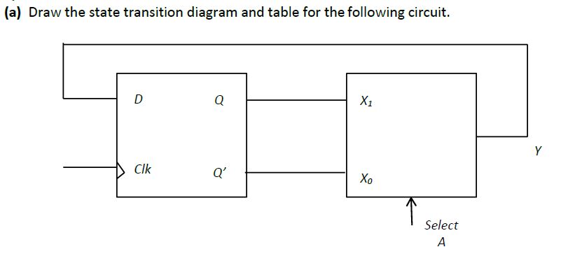
state transition diagram and table
Homework Answers
Request Answer!
We need at least 10 more requests to produce the answer.
0 / 10 have requested this problem solution
The more requests, the faster the answer.
18. For the following circuit find the state transition table and the stato transition diagram. K...
 18. For the following circuit find the state transition table and the stato transition diagram. K Q CLOCK
18. For the following circuit find the state transition table and the stato transition diagram. K Q CLOCK
18. For the following circuit find the state transition table and the stato transition diagram. K Q CLOCK
Draw the Logic diagram and the state transition diagram for a sequential circuit with two T...
Draw the Logic diagram and the state transition diagram for a sequential circuit with two T flip-flops, FFA and FFB; one input X, with flip-flop inputs TA=XA+XB, TB=XA’, and output Z=X’(A+B).
2. A sequential circuit is given below. The states in the transition diagram are labeled AB, e.g., the state corresponding to the sequential circuit are X and Y, and its output is Z. Draw a complete...
 2. A sequential circuit is given below. The states in the transition diagram are labeled AB, e.g., the state corresponding to the sequential circuit are X and Y, and its output is Z. Draw a complete state transition diagram for the circuit. J. A
2. A sequential circuit is given below. The states in the transition diagram are labeled AB, e.g., the state corresponding to the sequential circuit are X and Y, and its output is Z. Draw a complete...
2. A sequential circuit is given below. The states in the transition diagram are labeled AB, e.g., the state corresponding to the sequential circuit are X and Y, and its output is Z. Draw a complete state transition diagram for the circuit. J. A
2. A sequential circuit is given below. The states in the transition diagram are labeled AB, e.g., the state corresponding to the sequential circuit are X and Y, and its output is Z. Draw a complete...
5) (Optional) Design a circuit realizing the transition table shown below. Table 1: Pre-Lab Transition Table...
5) (Optional) Design a circuit realizing the transition table shown below. Table 1: Pre-Lab Transition Table PRESENT STATE NEXT STATE A B C NA NB NC 0 0 0 1 0 0 0 0 1 1 0 0 0 1 0 1 0 1 0 1 1 0 0 1 1 0 0 1 1 0 1 0 1 1 1 0 1 1 0 1 1 1 1 1 1 0 1 1 Find expressions for: NA = NB...
26. A counter is shown below. К, Q, К Q, CLOCK a. Find the state transition table and diagram. b....
 26. A counter is shown below. К, Q, К Q, CLOCK a. Find the state transition table and diagram. b. Show the count sequence. c. What is the mod of this counter? d. Modify this circuit so that it becomes self-starting, ie. it can enter the count sequence from any initial state. 13
26. A counter is shown below. К, Q, К Q, CLOCK a. Find the state transition table and diagram. b. Show the count sequence. c. What is...
26. A counter is shown below. К, Q, К Q, CLOCK a. Find the state transition table and diagram. b. Show the count sequence. c. What is the mod of this counter? d. Modify this circuit so that it becomes self-starting, ie. it can enter the count sequence from any initial state. 13
26. A counter is shown below. К, Q, К Q, CLOCK a. Find the state transition table and diagram. b. Show the count sequence. c. What is...
Analyze the sequential counter circuit shown in figure 5.1. Derive the state transition table and diagram....
 Analyze the sequential counter
circuit shown in figure 5.1. Derive the state transition table and
diagram.
7400 U1 7400 01. 74x73 U2 4 74x13 76x73 Ly, QH122 7400 Reset (11) Clock - Figure 5.1
Analyze the sequential counter
circuit shown in figure 5.1. Derive the state transition table and
diagram.
7400 U1 7400 01. 74x73 U2 4 74x13 76x73 Ly, QH122 7400 Reset (11) Clock - Figure 5.1
Table Q4.1 shows the state transition table for a finite state machine (FSM) with one input...
 Table Q4.1 shows the state transition table for a finite state
machine (FSM) with one input x, one output z and eight states.
(a) Copy the table of Table Q4.2 into your examination book and
determine the states and outputs for the input listed, assuming a
start current state of ‘1’. Determine what function the FSM is
performing.
(b) Using the implication chart method, determine the minimal
number of states. Show clearly your analysis.
(c) Draw the reduced state transition...
Table Q4.1 shows the state transition table for a finite state
machine (FSM) with one input x, one output z and eight states.
(a) Copy the table of Table Q4.2 into your examination book and
determine the states and outputs for the input listed, assuming a
start current state of ‘1’. Determine what function the FSM is
performing.
(b) Using the implication chart method, determine the minimal
number of states. Show clearly your analysis.
(c) Draw the reduced state transition...
Thc state transition table bclow is for a sequential circuit with onc input X and onc output Y. The circuit has two state variables A and B, and synchronous input Reset that resets the circuit to sta...
 Thc state transition table bclow is for a sequential circuit with onc input X and onc output Y. The circuit has two state variables A and B, and synchronous input Reset that resets the circuit to state AB-01 when Reset 1: Present State Next State Output X-0 A B A B 0 Reset State 0 0 (9 points) Implement the sequential circuit using minimum number of logic gates and rising- edge triggered D-FFs and draw the logic diagram of the...
Software Engineering Question Use an example to explain state transition diagram and draw the diagram.
Software Engineering Question Use an example to explain state transition diagram and draw the diagram.
Draw a state diagram and state table and show what if anything is wrong with the following synchronous state machine
 1. (a) Draw a state diagram and state table and show what if anything is wrong with the following synchronous state machine that has asynchronous input \(\mathrm{X}\) and state variables \(\mathrm{A} \& \mathrm{~B}\) ?(b) If possible, draw a new circuit (without adding or removing any flip-flops) that has the same functionality but fixes any problem with the circuit. Also, show the new state diagram and state table.
 18. For the following circuit find the state transition table and the stato transition diagram. K Q CLOCK
18. For the following circuit find the state transition table and the stato transition diagram. K Q CLOCK
18. For the following circuit find the state transition table and the stato transition diagram. K Q CLOCK
 2. A sequential circuit is given below. The states in the transition diagram are labeled AB, e.g., the state corresponding to the sequential circuit are X and Y, and its output is Z. Draw a complete state transition diagram for the circuit. J. A
2. A sequential circuit is given below. The states in the transition diagram are labeled AB, e.g., the state corresponding to the sequential circuit are X and Y, and its output is Z. Draw a complete...
2. A sequential circuit is given below. The states in the transition diagram are labeled AB, e.g., the state corresponding to the sequential circuit are X and Y, and its output is Z. Draw a complete state transition diagram for the circuit. J. A
2. A sequential circuit is given below. The states in the transition diagram are labeled AB, e.g., the state corresponding to the sequential circuit are X and Y, and its output is Z. Draw a complete...
 26. A counter is shown below. К, Q, К Q, CLOCK a. Find the state transition table and diagram. b. Show the count sequence. c. What is the mod of this counter? d. Modify this circuit so that it becomes self-starting, ie. it can enter the count sequence from any initial state. 13
26. A counter is shown below. К, Q, К Q, CLOCK a. Find the state transition table and diagram. b. Show the count sequence. c. What is...
26. A counter is shown below. К, Q, К Q, CLOCK a. Find the state transition table and diagram. b. Show the count sequence. c. What is the mod of this counter? d. Modify this circuit so that it becomes self-starting, ie. it can enter the count sequence from any initial state. 13
26. A counter is shown below. К, Q, К Q, CLOCK a. Find the state transition table and diagram. b. Show the count sequence. c. What is...
 Analyze the sequential counter
circuit shown in figure 5.1. Derive the state transition table and
diagram.
7400 U1 7400 01. 74x73 U2 4 74x13 76x73 Ly, QH122 7400 Reset (11) Clock - Figure 5.1
Analyze the sequential counter
circuit shown in figure 5.1. Derive the state transition table and
diagram.
7400 U1 7400 01. 74x73 U2 4 74x13 76x73 Ly, QH122 7400 Reset (11) Clock - Figure 5.1
 Table Q4.1 shows the state transition table for a finite state
machine (FSM) with one input x, one output z and eight states.
(a) Copy the table of Table Q4.2 into your examination book and
determine the states and outputs for the input listed, assuming a
start current state of ‘1’. Determine what function the FSM is
performing.
(b) Using the implication chart method, determine the minimal
number of states. Show clearly your analysis.
(c) Draw the reduced state transition...
Table Q4.1 shows the state transition table for a finite state
machine (FSM) with one input x, one output z and eight states.
(a) Copy the table of Table Q4.2 into your examination book and
determine the states and outputs for the input listed, assuming a
start current state of ‘1’. Determine what function the FSM is
performing.
(b) Using the implication chart method, determine the minimal
number of states. Show clearly your analysis.
(c) Draw the reduced state transition...
 Thc state transition table bclow is for a sequential circuit with onc input X and onc output Y. The circuit has two state variables A and B, and synchronous input Reset that resets the circuit to state AB-01 when Reset 1: Present State Next State Output X-0 A B A B 0 Reset State 0 0 (9 points) Implement the sequential circuit using minimum number of logic gates and rising- edge triggered D-FFs and draw the logic diagram of the...
 1. (a) Draw a state diagram and state table and show what if anything is wrong with the following synchronous state machine that has asynchronous input \(\mathrm{X}\) and state variables \(\mathrm{A} \& \mathrm{~B}\) ?(b) If possible, draw a new circuit (without adding or removing any flip-flops) that has the same functionality but fixes any problem with the circuit. Also, show the new state diagram and state table.
Most questions answered within 3 hours.
-
Where is the error in this code sequence?
String s1 = "Hello";
String s2 = "ello";...
asked 10 months ago -
Financial data for Joel de Paris, Inc., for last year
follow:
Joel de Paris, Inc.
Balance...
asked 10 months ago -
Consider this reaction:
Al2(SO4)3 (aq)+ BaCl3
(aq) Al2Cl6 (aq)- +
3BaSO4(s) . What is the...
asked 10 months ago -
Suppose that Savneet is considering increasing her
recent random sample from 20 car rentals to 40...
asked 10 months ago -
Trucks arrive at an unloading terminal at an average rate of 120
per hour.
Trucks arrive...
asked 10 months ago -
Why are methanol and ethanol completely soluble in water while
octanol is not very little soluble....
asked 10 months ago -
A facilities manager at a university reads in a research report
that the mean amount of...
asked 10 months ago -
When the CuSO4 is rehydrated by adding water to the anhydrous
compound, is this an endothermic...
asked 10 months ago -
A ray of sunlight is passing from diamond into crown glass; the
angle of incidence is...
asked 10 months ago -
A block of mass 0.249 kg is placed on top of a light, vertical
spring of...
asked 10 months ago -
how do the kidneys compensate in the presences of acidosis
a) trigger hyperventilate
b) reserve acid...
asked 10 months ago -
Question 501 pts
The rental rate of capital to the firm increases. Which of the
following...
asked 10 months ago