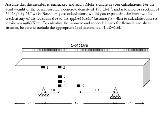
For the beam shown below, determine the flexural stresses, shear stresses, principal stresses,
and the angle to the principle stress plane at the locations shown. Can you solve Location one and 4 first< then as many other as you can please?
Locations 1 and 2 are at the top of the beam, while locations 5 and 6 are at the bottom.
Location 3 is at the beam mid-height, while location 4 is midway between locations 3 and 5.
Homework Answers


Add Answer to:
For the beam shown below, determine the flexural stresses, shear
stresses, principal stresses,
and the angle...
(a) Determine the maximum compressive and tensile normal stresses in the A-36 structural steel beam shown...
 (a) Determine the maximum compressive and tensile normal
stresses in the A-36 structural steel beam shown and define their
locations (location along the beam and on the cross section). (b)
Determine the deflection of point B using the double
integration method. The height of the cross section shown (in the
y-direction) is 5 inches and width (in the
z-direction) is 10 inches, and the average thickness
throughout is 0.5 inches. (Use elastic properties for all
calculations)
ANSWER: (a) max tensile...
(a) Determine the maximum compressive and tensile normal
stresses in the A-36 structural steel beam shown and define their
locations (location along the beam and on the cross section). (b)
Determine the deflection of point B using the double
integration method. The height of the cross section shown (in the
y-direction) is 5 inches and width (in the
z-direction) is 10 inches, and the average thickness
throughout is 0.5 inches. (Use elastic properties for all
calculations)
ANSWER: (a) max tensile...
An elevation of a concrete frame is shown below. A superimposed dead load of 200 lb/ft and a live load of 600 lb/ft are to be supported in addition to the beam self-weight. The beam's cross-...
 An elevation of a concrete frame is shown below. A superimposed dead load of 200 lb/ft and a live load of 600 lb/ft are to be supported in addition to the beam self-weight. The beam's cross- section is shown as well. The weight density of reinforced concrete is 150 lbs/eu. ft. Use 1.2D+1.6L as your load combination. Use ACI moment coefficients and statics, as appropriate, to provide the Mu values for points A, B, C, and D. 48 5" 15"...
2. The box beam is subjected to the loading shown. Determine the principal stresses in the...
 2. The box beam is subjected to the loading shown. Determine the principal stresses in the beam at point A, marked in red. 800 lb 1200 lb 5 in. . A 5 in.I A18 in. 8 in. 63 -3 ft- -5 ft 42.5 4-1-2.5 t-
23. For the concrete cantilever beam shown below (L=8 ft), draw the proper location and details for the flexural reinfo...
 23. For the concrete cantilever beam shown below (L=8 ft), draw the proper location and details for the flexural reinforcement of area, As, on the elevation (including connection at support) and cross section. Assume that 3 #8's are used for flexural reinforcement with 2-leg #4 stirrups for shear (spaced at 6 in on center) and 1.5-in cover (over the stirrups). [2 PT] Concentrated load height, h-16 in width, b-12 in; f' 5000 psi Support Elevation Cross Section 24. [9 PT]...
1. For the overhanging beam in the figure below, determine the maximum shear stress, the maximum...
 1. For the overhanging beam in the figure below, determine the maximum shear stress, the maximum tensile stress, and the maximum compressive stress in the beam due to the loading shown. 300 lb/ft 6 in. 1 in. 4 ft 10 ft 1 in. 2 in. Section INSTRUCTIONS For PROBLEM do the following steps: 1. Show ALL your work 2. Draw appropriately labeled FBDs 3. Use appropriate segments to develop expressions for the shear force and bending moment. diagrams in a...
Reinforced Concrete For the singly-reinforced beam shown below, determine the concrete and steel stresses at the...
 Reinforced Concrete
For the singly-reinforced beam shown below, determine the concrete and steel stresses at the location of the maximum positive and negative moments. Use: modular ratio = 9. Has the beam already cracked? If the allowable concrete stresses are: concrete = 9MPa and steel = 138MPa, could this beam resist the maximum stresses experienced by the beam without failure? (Prove with solution.) 30 kN/m 16 J 530 mm 250mm Whe 250mm 1m Q
Reinforced Concrete
For the singly-reinforced beam shown below, determine the concrete and steel stresses at the location of the maximum positive and negative moments. Use: modular ratio = 9. Has the beam already cracked? If the allowable concrete stresses are: concrete = 9MPa and steel = 138MPa, could this beam resist the maximum stresses experienced by the beam without failure? (Prove with solution.) 30 kN/m 16 J 530 mm 250mm Whe 250mm 1m Q
4. SHEAR AND MOMENT DIAGRAMS Determine the shear and moment diagrams for the beam shown below....
 4. SHEAR AND MOMENT DIAGRAMS Determine the shear and moment diagrams for the beam shown below. There is a pin at A and a rocker at B. a. There are 3 sections. Draw the FBD for each section. Also, give the shear and moment equation for each section. 125 lb/ft 1000 lb х 10 ft 6 ft 10 ft
Based on tributary load analysis, the dead and live loads, wd and wų, respectively, acting on...
 Based on tributary load analysis, the dead and live loads, wd and wų, respectively, acting on a beam in a vertical load resisting system are shown below. The concrete is normalweight with compressive strength f=5000 psi. Note that the given dead load includes the self-weight of the beam and slab. Section wp=1.2 kip/ft, wu=1.5 kip/ft be-45 inch 5 inch 1 30 inch B A 10 inch In=10 ft 1. Design and detail the beam for positive flexure at section A....
4. SHEAR AND MOMENT DIAGRAMS Determine the shear and moment diagrams for the beam shown below....
 4. SHEAR AND MOMENT DIAGRAMS Determine the shear and moment diagrams for the beam shown below. There is a pin at A and a rocker at B. a. There are 3 sections. Draw the FBD for each section. Also, give the shear and moment equation for each section. у 125 lb/ft 1000 lb х A 10 ft B 6 ft 10 ft
 (a) Determine the maximum compressive and tensile normal
stresses in the A-36 structural steel beam shown and define their
locations (location along the beam and on the cross section). (b)
Determine the deflection of point B using the double
integration method. The height of the cross section shown (in the
y-direction) is 5 inches and width (in the
z-direction) is 10 inches, and the average thickness
throughout is 0.5 inches. (Use elastic properties for all
calculations)
ANSWER: (a) max tensile...
(a) Determine the maximum compressive and tensile normal
stresses in the A-36 structural steel beam shown and define their
locations (location along the beam and on the cross section). (b)
Determine the deflection of point B using the double
integration method. The height of the cross section shown (in the
y-direction) is 5 inches and width (in the
z-direction) is 10 inches, and the average thickness
throughout is 0.5 inches. (Use elastic properties for all
calculations)
ANSWER: (a) max tensile...
 An elevation of a concrete frame is shown below. A superimposed dead load of 200 lb/ft and a live load of 600 lb/ft are to be supported in addition to the beam self-weight. The beam's cross- section is shown as well. The weight density of reinforced concrete is 150 lbs/eu. ft. Use 1.2D+1.6L as your load combination. Use ACI moment coefficients and statics, as appropriate, to provide the Mu values for points A, B, C, and D. 48 5" 15"...
 2. The box beam is subjected to the loading shown. Determine the principal stresses in the beam at point A, marked in red. 800 lb 1200 lb 5 in. . A 5 in.I A18 in. 8 in. 63 -3 ft- -5 ft 42.5 4-1-2.5 t-
 23. For the concrete cantilever beam shown below (L=8 ft), draw the proper location and details for the flexural reinforcement of area, As, on the elevation (including connection at support) and cross section. Assume that 3 #8's are used for flexural reinforcement with 2-leg #4 stirrups for shear (spaced at 6 in on center) and 1.5-in cover (over the stirrups). [2 PT] Concentrated load height, h-16 in width, b-12 in; f' 5000 psi Support Elevation Cross Section 24. [9 PT]...
 23. For the concrete cantilever beam shown below (L=8 ft), draw the proper location and details for the flexural reinforcement of area, As, on the elevation (including connection at support) and cross section. Assume that 3 #8's are used for flexural reinforcement with 2-leg #4 stirrups for shear (spaced at 6 in on center) and 1.5-in cover (over the stirrups). [2 PT] Concentrated load height, h-16 in width, b-12 in; f' 5000 psi Support Elevation Cross Section 24. [9 PT]...
 1. For the overhanging beam in the figure below, determine the maximum shear stress, the maximum tensile stress, and the maximum compressive stress in the beam due to the loading shown. 300 lb/ft 6 in. 1 in. 4 ft 10 ft 1 in. 2 in. Section INSTRUCTIONS For PROBLEM do the following steps: 1. Show ALL your work 2. Draw appropriately labeled FBDs 3. Use appropriate segments to develop expressions for the shear force and bending moment. diagrams in a...
 Reinforced Concrete
For the singly-reinforced beam shown below, determine the concrete and steel stresses at the location of the maximum positive and negative moments. Use: modular ratio = 9. Has the beam already cracked? If the allowable concrete stresses are: concrete = 9MPa and steel = 138MPa, could this beam resist the maximum stresses experienced by the beam without failure? (Prove with solution.) 30 kN/m 16 J 530 mm 250mm Whe 250mm 1m Q
Reinforced Concrete
For the singly-reinforced beam shown below, determine the concrete and steel stresses at the location of the maximum positive and negative moments. Use: modular ratio = 9. Has the beam already cracked? If the allowable concrete stresses are: concrete = 9MPa and steel = 138MPa, could this beam resist the maximum stresses experienced by the beam without failure? (Prove with solution.) 30 kN/m 16 J 530 mm 250mm Whe 250mm 1m Q
 4. SHEAR AND MOMENT DIAGRAMS Determine the shear and moment diagrams for the beam shown below. There is a pin at A and a rocker at B. a. There are 3 sections. Draw the FBD for each section. Also, give the shear and moment equation for each section. 125 lb/ft 1000 lb х 10 ft 6 ft 10 ft
 Based on tributary load analysis, the dead and live loads, wd and wų, respectively, acting on a beam in a vertical load resisting system are shown below. The concrete is normalweight with compressive strength f=5000 psi. Note that the given dead load includes the self-weight of the beam and slab. Section wp=1.2 kip/ft, wu=1.5 kip/ft be-45 inch 5 inch 1 30 inch B A 10 inch In=10 ft 1. Design and detail the beam for positive flexure at section A....
 4. SHEAR AND MOMENT DIAGRAMS Determine the shear and moment diagrams for the beam shown below. There is a pin at A and a rocker at B. a. There are 3 sections. Draw the FBD for each section. Also, give the shear and moment equation for each section. у 125 lb/ft 1000 lb х A 10 ft B 6 ft 10 ft
Most questions answered within 3 hours.
-
Where is the error in this code sequence?
String s1 = "Hello";
String s2 = "ello";...
asked 10 months ago -
Financial data for Joel de Paris, Inc., for last year
follow:
Joel de Paris, Inc.
Balance...
asked 10 months ago -
Consider this reaction:
Al2(SO4)3 (aq)+ BaCl3
(aq) Al2Cl6 (aq)- +
3BaSO4(s) . What is the...
asked 10 months ago -
Suppose that Savneet is considering increasing her
recent random sample from 20 car rentals to 40...
asked 10 months ago -
Trucks arrive at an unloading terminal at an average rate of 120
per hour.
Trucks arrive...
asked 10 months ago -
Why are methanol and ethanol completely soluble in water while
octanol is not very little soluble....
asked 10 months ago -
A facilities manager at a university reads in a research report
that the mean amount of...
asked 10 months ago -
When the CuSO4 is rehydrated by adding water to the anhydrous
compound, is this an endothermic...
asked 10 months ago -
A ray of sunlight is passing from diamond into crown glass; the
angle of incidence is...
asked 10 months ago -
A block of mass 0.249 kg is placed on top of a light, vertical
spring of...
asked 10 months ago -
how do the kidneys compensate in the presences of acidosis
a) trigger hyperventilate
b) reserve acid...
asked 10 months ago -
Question 501 pts
The rental rate of capital to the firm increases. Which of the
following...
asked 10 months ago