
Homework Answers

Add Answer to:
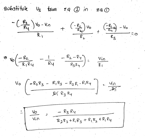
Figure 1 Q 3. For the circuit in figure 2 find Vo/V. (25 Points) R, 2...
Q1. The values of the difference amplifier in figure 1 are Ao 5x 10⁵, Rı =...
 Q1. The values of the difference amplifier in figure 1 are Ao 5x 10⁵, Rı = 5kQ, RF = 50M, Ra-2kQ, and Rx-20kS2. The input voltages are vb-5mV and Va--15mV. Find the out voltage vo. (5 Points) RF R1 Figure 1 Q2. Design an integrator as shown in figure 2 to be operated with an AC signal of 5 kHz and to give a closed loop voltage gain of Af-10 at w=1 rad/s. (5 Points) iRF RI 79 +Vcc 2...
Problem 1 (25 points) Design a diode clamper circuit to generate the output Vo given the...
 Problem 1 (25 points) Design a diode clamper circuit to generate the output Vo given the input signal Vi as shown in the figure below: VI Vo A 35 10 5 -20 Design the circuit for two cases: a) (15 points) Vy -0 b) (10 points) V,0.7 V
Design a band pass filter (BPF) with a circuit shown below (ie find R, R, RF,...
 Design a band pass filter (BPF) with a circuit shown below (ie find R, R, RF, RF) Assume: fi2 kHz f=100 Hz A.A 2 (the overall gain) Ci=0.01 uF Cl'-05pF R1-R1 - 10 K I R C1 Vi R Vo RF RF R1 R1 1 Hint: J2TRC
Design a band pass filter (BPF) with a circuit shown below (ie find R, R, RF, RF) Assume: fi2 kHz f=100 Hz A.A 2 (the overall gain) Ci=0.01 uF Cl'-05pF R1-R1 - 10...
Design a band pass filter (BPF) with a circuit shown below (ie find R, R, RF, RF) Assume: fi2 kHz f=100 Hz A.A 2 (the overall gain) Ci=0.01 uF Cl'-05pF R1-R1 - 10 K I R C1 Vi R Vo RF RF R1 R1 1 Hint: J2TRC
Design a band pass filter (BPF) with a circuit shown below (ie find R, R, RF, RF) Assume: fi2 kHz f=100 Hz A.A 2 (the overall gain) Ci=0.01 uF Cl'-05pF R1-R1 - 10...
The circuit shown in Figure Q4-1 includes an audio source and the equivalent circuit of a...
 The circuit shown in Figure Q4-1 includes an audio source and the equivalent circuit of a loudspeaker that you have been asked to analyse. 4. a) Assuming the speaker is to operate at a single frequency of 200 Hz and is5 driven by a cosinusoidal signal with peak amplitude of 20 V; determine the equivalent impedance of the speaker When connected to the audio source, calculate the current flow i() When testing the loudspeaker detailed in Q4a) i), you can...
Problem 3 (30 points): For the circuit in Fig. 3, v, has an RMS value of...
 Problem 3 (30 points): For the circuit in Fig. 3, v, has an RMS value of 9.0 V and a frequency of 60 Hz. Assume that R-20 Ω and that V,-0.7 V for each diode. Vs R o Figure 3: Circuit for Problem 3 (10 points) 1. Find the maximum value of Vo 2. Find the value of C to guarantee a ripple voltage of 0.25 V or less. (10 points) 3. For what fraction of the time is the...
2. H(s)Vo/v, for the circuit shown in Figure P9-12. 1 ΜΩ Figure P9-12 2. H(s)Vo/v, for the circuit shown in Figure P9-12. 1 ΜΩ Figure P9-12
 2. H(s)Vo/v, for the circuit shown in Figure P9-12. 1 ΜΩ Figure P9-12
2. H(s)Vo/v, for the circuit shown in Figure P9-12. 1 ΜΩ Figure P9-12
2. H(s)Vo/v, for the circuit shown in Figure P9-12. 1 ΜΩ Figure P9-12
ONLY NEED HELP WITH C AND D PLEASE! The differentiator circuit shown in Figure 1 uses an op-amp with ideal characteristics C1 Figure 1 (a) Prove that the gain of the circuit is given by the following...
 ONLY NEED HELP WITH C AND D PLEASE!
The differentiator circuit shown in Figure 1 uses an op-amp with ideal characteristics C1 Figure 1 (a) Prove that the gain of the circuit is given by the following expression using first principles for an ideal op-amp (2 marks) Gain = - (1 + juli R 1) (b) If the differentiator frequency (at unity gain) is 100Hz and the high frequency gain is 40dB and R2 is 220kQ, design the rest of...
ONLY NEED HELP WITH C AND D PLEASE!
The differentiator circuit shown in Figure 1 uses an op-amp with ideal characteristics C1 Figure 1 (a) Prove that the gain of the circuit is given by the following expression using first principles for an ideal op-amp (2 marks) Gain = - (1 + juli R 1) (b) If the differentiator frequency (at unity gain) is 100Hz and the high frequency gain is 40dB and R2 is 220kQ, design the rest of...
14. Problem For the circuit in figure below, find the steady-state output voltage vo (t). The inp...
 14. Problem For the circuit in figure below, find the steady-state output voltage vo (t). The input signal is v (t) and C = 5 μF 4-2 cos 100t, R 1 kΩ Do C R 12 U)
14. Problem For the circuit in figure below, find the steady-state output voltage vo (t). The input signal is v (t) and C = 5 μF 4-2 cos 100t, R 1 kΩ Do C R 12 U)
14. Problem For the circuit in figure below, find the steady-state output voltage vo (t). The input signal is v (t) and C = 5 μF 4-2 cos 100t, R 1 kΩ Do C R 12 U)
In the voltage-divider circuit shown in the figure, the no-load value of vo is 5 V...
 In the voltage-divider circuit shown in the figure, the no-load value of vo is 5 V When the load resistance RI is attached across the terminals a and b, vo drops to 3 V.(Figure 1) PartA Find RL Express your answer with the appropriate units RI-7.28 Submit Previous Answers Request Answer Incorrect, Try Again: One attempt remaining Provide Feedback igure 1 of 1 40Ω 20 V R2 vo
need help with C and D please The differentiator circuit shown in Figure 1 uses an op-amp with ideal characteristics. R2 R1 C1 Vi O Figure 1 (c) Sketch the Bode magnitude response for this circ...
 need help with C and D please
The differentiator circuit shown in Figure 1 uses an op-amp with ideal characteristics. R2 R1 C1 Vi O Figure 1 (c) Sketch the Bode magnitude response for this circuit for the frequency range of 10° to 108 Hz. (7 marks) (d) Sketch the output waveform of the differentiator and justify your answer, if v is as shown in Figure 2 with a period of: () 100 ms (ii) 10 us (6 marks) 0.11...
need help with C and D please
The differentiator circuit shown in Figure 1 uses an op-amp with ideal characteristics. R2 R1 C1 Vi O Figure 1 (c) Sketch the Bode magnitude response for this circuit for the frequency range of 10° to 108 Hz. (7 marks) (d) Sketch the output waveform of the differentiator and justify your answer, if v is as shown in Figure 2 with a period of: () 100 ms (ii) 10 us (6 marks) 0.11...
 Q1. The values of the difference amplifier in figure 1 are Ao 5x 10⁵, Rı = 5kQ, RF = 50M, Ra-2kQ, and Rx-20kS2. The input voltages are vb-5mV and Va--15mV. Find the out voltage vo. (5 Points) RF R1 Figure 1 Q2. Design an integrator as shown in figure 2 to be operated with an AC signal of 5 kHz and to give a closed loop voltage gain of Af-10 at w=1 rad/s. (5 Points) iRF RI 79 +Vcc 2...
 Problem 1 (25 points) Design a diode clamper circuit to generate the output Vo given the input signal Vi as shown in the figure below: VI Vo A 35 10 5 -20 Design the circuit for two cases: a) (15 points) Vy -0 b) (10 points) V,0.7 V
 Design a band pass filter (BPF) with a circuit shown below (ie find R, R, RF, RF) Assume: fi2 kHz f=100 Hz A.A 2 (the overall gain) Ci=0.01 uF Cl'-05pF R1-R1 - 10 K I R C1 Vi R Vo RF RF R1 R1 1 Hint: J2TRC
Design a band pass filter (BPF) with a circuit shown below (ie find R, R, RF, RF) Assume: fi2 kHz f=100 Hz A.A 2 (the overall gain) Ci=0.01 uF Cl'-05pF R1-R1 - 10...
Design a band pass filter (BPF) with a circuit shown below (ie find R, R, RF, RF) Assume: fi2 kHz f=100 Hz A.A 2 (the overall gain) Ci=0.01 uF Cl'-05pF R1-R1 - 10 K I R C1 Vi R Vo RF RF R1 R1 1 Hint: J2TRC
Design a band pass filter (BPF) with a circuit shown below (ie find R, R, RF, RF) Assume: fi2 kHz f=100 Hz A.A 2 (the overall gain) Ci=0.01 uF Cl'-05pF R1-R1 - 10...
 The circuit shown in Figure Q4-1 includes an audio source and the equivalent circuit of a loudspeaker that you have been asked to analyse. 4. a) Assuming the speaker is to operate at a single frequency of 200 Hz and is5 driven by a cosinusoidal signal with peak amplitude of 20 V; determine the equivalent impedance of the speaker When connected to the audio source, calculate the current flow i() When testing the loudspeaker detailed in Q4a) i), you can...
 Problem 3 (30 points): For the circuit in Fig. 3, v, has an RMS value of 9.0 V and a frequency of 60 Hz. Assume that R-20 Ω and that V,-0.7 V for each diode. Vs R o Figure 3: Circuit for Problem 3 (10 points) 1. Find the maximum value of Vo 2. Find the value of C to guarantee a ripple voltage of 0.25 V or less. (10 points) 3. For what fraction of the time is the...
 2. H(s)Vo/v, for the circuit shown in Figure P9-12. 1 ΜΩ Figure P9-12
2. H(s)Vo/v, for the circuit shown in Figure P9-12. 1 ΜΩ Figure P9-12
2. H(s)Vo/v, for the circuit shown in Figure P9-12. 1 ΜΩ Figure P9-12
 ONLY NEED HELP WITH C AND D PLEASE!
The differentiator circuit shown in Figure 1 uses an op-amp with ideal characteristics C1 Figure 1 (a) Prove that the gain of the circuit is given by the following expression using first principles for an ideal op-amp (2 marks) Gain = - (1 + juli R 1) (b) If the differentiator frequency (at unity gain) is 100Hz and the high frequency gain is 40dB and R2 is 220kQ, design the rest of...
ONLY NEED HELP WITH C AND D PLEASE!
The differentiator circuit shown in Figure 1 uses an op-amp with ideal characteristics C1 Figure 1 (a) Prove that the gain of the circuit is given by the following expression using first principles for an ideal op-amp (2 marks) Gain = - (1 + juli R 1) (b) If the differentiator frequency (at unity gain) is 100Hz and the high frequency gain is 40dB and R2 is 220kQ, design the rest of...
 14. Problem For the circuit in figure below, find the steady-state output voltage vo (t). The input signal is v (t) and C = 5 μF 4-2 cos 100t, R 1 kΩ Do C R 12 U)
14. Problem For the circuit in figure below, find the steady-state output voltage vo (t). The input signal is v (t) and C = 5 μF 4-2 cos 100t, R 1 kΩ Do C R 12 U)
14. Problem For the circuit in figure below, find the steady-state output voltage vo (t). The input signal is v (t) and C = 5 μF 4-2 cos 100t, R 1 kΩ Do C R 12 U)
 In the voltage-divider circuit shown in the figure, the no-load value of vo is 5 V When the load resistance RI is attached across the terminals a and b, vo drops to 3 V.(Figure 1) PartA Find RL Express your answer with the appropriate units RI-7.28 Submit Previous Answers Request Answer Incorrect, Try Again: One attempt remaining Provide Feedback igure 1 of 1 40Ω 20 V R2 vo
 need help with C and D please
The differentiator circuit shown in Figure 1 uses an op-amp with ideal characteristics. R2 R1 C1 Vi O Figure 1 (c) Sketch the Bode magnitude response for this circuit for the frequency range of 10° to 108 Hz. (7 marks) (d) Sketch the output waveform of the differentiator and justify your answer, if v is as shown in Figure 2 with a period of: () 100 ms (ii) 10 us (6 marks) 0.11...
need help with C and D please
The differentiator circuit shown in Figure 1 uses an op-amp with ideal characteristics. R2 R1 C1 Vi O Figure 1 (c) Sketch the Bode magnitude response for this circuit for the frequency range of 10° to 108 Hz. (7 marks) (d) Sketch the output waveform of the differentiator and justify your answer, if v is as shown in Figure 2 with a period of: () 100 ms (ii) 10 us (6 marks) 0.11...
Most questions answered within 3 hours.
-
Where is the error in this code sequence?
String s1 = "Hello";
String s2 = "ello";...
asked 11 months ago -
Financial data for Joel de Paris, Inc., for last year
follow:
Joel de Paris, Inc.
Balance...
asked 11 months ago -
Consider this reaction:
Al2(SO4)3 (aq)+ BaCl3
(aq) Al2Cl6 (aq)- +
3BaSO4(s) . What is the...
asked 11 months ago -
Suppose that Savneet is considering increasing her
recent random sample from 20 car rentals to 40...
asked 11 months ago -
Trucks arrive at an unloading terminal at an average rate of 120
per hour.
Trucks arrive...
asked 11 months ago -
Why are methanol and ethanol completely soluble in water while
octanol is not very little soluble....
asked 11 months ago -
A facilities manager at a university reads in a research report
that the mean amount of...
asked 11 months ago -
When the CuSO4 is rehydrated by adding water to the anhydrous
compound, is this an endothermic...
asked 11 months ago -
A ray of sunlight is passing from diamond into crown glass; the
angle of incidence is...
asked 11 months ago -
A block of mass 0.249 kg is placed on top of a light, vertical
spring of...
asked 11 months ago -
how do the kidneys compensate in the presences of acidosis
a) trigger hyperventilate
b) reserve acid...
asked 11 months ago -
Question 501 pts
The rental rate of capital to the firm increases. Which of the
following...
asked 11 months ago