
Homework Answers


a) The general expression for two dependent variables are


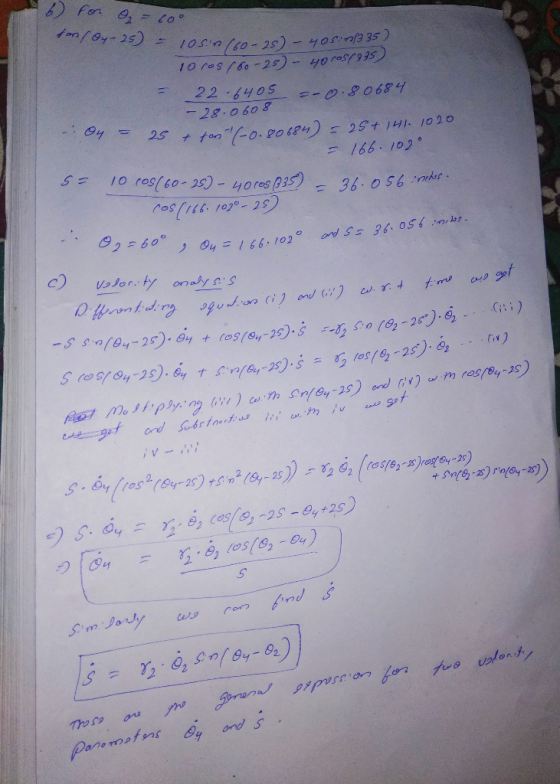
b) For 
c) The general expression for two velocity parameters are


d) For 
Add Answer to:
Question + 130 marks An inverted low. The -10 in totales verted crank-slider mechanism is shown...
5. An inverted crank sider mechanism is shown below. The crank length is 20 cm. The...
 5. An inverted crank sider mechanism is shown below. The crank length is 20 cm. The length of the ground link is 50 cm. The crank rotates at a constant angular velocity of 2000 rpm (ccw) The crank shaft and the follower are considered massless in this problem. The slider as a coupler has a mass of 0.25 kg with a mass center as A3, and a mass moment of inertia of 0.125 kg-m i) Conduct the kinematical analysis by...
Ection Il-Slider Crank Mechanism Use Figure I and the information below to answer questions 3,4 a...
 please answer all
ection Il-Slider Crank Mechanism Use Figure I and the information below to answer questions 3,4 and S FigureI INot drawn to scalel D connecting rodplston The diagram in Figure 1 above displays a simple schematic diagram of a Slider Crank Mechanism The crank link (i.e. #4) turns counterclockwise by a motor at 1250 rpm. The length of the coupler link (ie. label #3) is 6.375 inches long and the maximum displacement for this mechanism is 3.0 inches....
please answer all
ection Il-Slider Crank Mechanism Use Figure I and the information below to answer questions 3,4 and S FigureI INot drawn to scalel D connecting rodplston The diagram in Figure 1 above displays a simple schematic diagram of a Slider Crank Mechanism The crank link (i.e. #4) turns counterclockwise by a motor at 1250 rpm. The length of the coupler link (ie. label #3) is 6.375 inches long and the maximum displacement for this mechanism is 3.0 inches....
or the mechanism shown, the crank (member 2) rotates with constant angular velocity o The slider...
 or the mechanism shown, the crank (member 2) rotates with constant angular velocity o The slider (member 3) slides inside a curved slot which has a radius of curvature of R (center of curvature at C4). By using complex number method: (i) Derive expressions for V (velocity of link 4) and A (acceleration of link 4) in terms of o2 and ф. (ii) Compute V and A for the case of R1.6", a-09", ф-35, and 02-10 rad/s CCW.
Question 4 (15 marks) The figure below shows a slider-crank mechanism. Link AB is driven with...
 Question 4 (15 marks) The figure below shows a slider-crank mechanism. Link AB is driven with a CONSTANT angular velocity of 4 rad/s. a) Determine the (vector) velocity of point B. b) Determine the angular velocity of link BC and the velocity of the slider at C. c) Determine the (vector) acceleration of point B. d) Determine the (vector) acceleration of the slider at C. 125 mm MAB = 4 rad/s 300 mm 600
In a slider crank mechanism at the given instant member AB (crank) has uniform angular motion...
 In a slider crank mechanism at the given instant member AB (crank) has uniform angular motion as shown. Draw the position and velocity diagrams of the mechanism and determine angular velocity of BC at this instant. [Remember: velocity of a rotating link, Vero] Name and ID and Sienature on the 7 in. 3 rad/s Sin. 5 in. Attach File
ine given 4) In the figure aside, an in-line slider- crank mechanism is shown. a) Calculate the velocity of the cou...
 ine given 4) In the figure aside, an in-line slider- crank mechanism is shown. a) Calculate the velocity of the coupler point D if crank AB is rotating CW wilth a speed of 2 rad/sec b) Calculate the necessary crank if the velocity of the coupler point is required to be 50 cm/sec, at the given position. speed AB 5am BC-10cm 0 30 degrees
ine given 4) In the figure aside, an in-line slider- crank mechanism is shown. a) Calculate...
ine given 4) In the figure aside, an in-line slider- crank mechanism is shown. a) Calculate the velocity of the coupler point D if crank AB is rotating CW wilth a speed of 2 rad/sec b) Calculate the necessary crank if the velocity of the coupler point is required to be 50 cm/sec, at the given position. speed AB 5am BC-10cm 0 30 degrees
ine given 4) In the figure aside, an in-line slider- crank mechanism is shown. a) Calculate...
An offset slider-crank mechanism consists of 4 links: Link 1: ground: a horizontal slider track that...
An offset slider-crank mechanism consists of 4 links: Link 1: ground: a horizontal slider track that passes through the origin O. Also, a fixed pivot at point A, located 50 in. above point O Link 2: moving, endpoints A & B, R = 10 in., ω2 = 10 deg/s ccw Link 3: moving, endpoints B & C, R = 65 in. Link 4: moving slider, point C, located to the right of the origin The working stroke is to the...
3. The unscaled diagram above shows a quick-return crank-slider pump mechanism. It is driven by a...
 3. The unscaled diagram above shows a quick-return crank-slider pump mechanism. It is driven by a motor that rotates the crank at constant speed. The coupler has a length (b) of 4", a 0.75" and c 1.0". Point B is the revolute joint between coupler and piston. Use graphical methods to do the following: (10%) Find the position of the linkage when the crank has rotated to the vertical position (e2-90°), and determine the X-coordinate of B (in inches) in...
PROBLEM 2 (20 points) In the offset slider crank mechanism shown, the crank (AB) has a constant angular velocity of 10 rad/s, counterclockwise (A) Draw (clearly) the two limiting positions of the...
 PROBLEM 2 (20 points) In the offset slider crank mechanism shown, the crank (AB) has a constant angular velocity of 10 rad/s, counterclockwise (A) Draw (clearly) the two limiting positions of the slider c (B) Determine the stroke of the slider and the time ratio of the mechanism (C) Determine the velocity ( with direction) of the slider at the instant 8- AB- 40 mm C-100mm
PROBLEM 2 (20 points) In the offset slider crank mechanism shown, the crank (AB)...
PROBLEM 2 (20 points) In the offset slider crank mechanism shown, the crank (AB) has a constant angular velocity of 10 rad/s, counterclockwise (A) Draw (clearly) the two limiting positions of the slider c (B) Determine the stroke of the slider and the time ratio of the mechanism (C) Determine the velocity ( with direction) of the slider at the instant 8- AB- 40 mm C-100mm
PROBLEM 2 (20 points) In the offset slider crank mechanism shown, the crank (AB)...
1. The offset slider-crank mechanism illustrated in Figure is driven by slider 4 at a velocity...
 1. The offset slider-crank mechanism illustrated in Figure is driven by slider 4 at a velocity Ve-101 m/s at the position shown. Determine the instantaneous velocity of point D and the angular velocities of links 2 and 3. Show details of your work to get full marks (20 points) 50 140 2 45. A(G 20 50 1 of
1. The offset slider-crank mechanism illustrated in Figure is driven by slider 4 at a velocity Ve-101 m/s at the position shown....
1. The offset slider-crank mechanism illustrated in Figure is driven by slider 4 at a velocity Ve-101 m/s at the position shown. Determine the instantaneous velocity of point D and the angular velocities of links 2 and 3. Show details of your work to get full marks (20 points) 50 140 2 45. A(G 20 50 1 of
1. The offset slider-crank mechanism illustrated in Figure is driven by slider 4 at a velocity Ve-101 m/s at the position shown....
 5. An inverted crank sider mechanism is shown below. The crank length is 20 cm. The length of the ground link is 50 cm. The crank rotates at a constant angular velocity of 2000 rpm (ccw) The crank shaft and the follower are considered massless in this problem. The slider as a coupler has a mass of 0.25 kg with a mass center as A3, and a mass moment of inertia of 0.125 kg-m i) Conduct the kinematical analysis by...
 please answer all
ection Il-Slider Crank Mechanism Use Figure I and the information below to answer questions 3,4 and S FigureI INot drawn to scalel D connecting rodplston The diagram in Figure 1 above displays a simple schematic diagram of a Slider Crank Mechanism The crank link (i.e. #4) turns counterclockwise by a motor at 1250 rpm. The length of the coupler link (ie. label #3) is 6.375 inches long and the maximum displacement for this mechanism is 3.0 inches....
please answer all
ection Il-Slider Crank Mechanism Use Figure I and the information below to answer questions 3,4 and S FigureI INot drawn to scalel D connecting rodplston The diagram in Figure 1 above displays a simple schematic diagram of a Slider Crank Mechanism The crank link (i.e. #4) turns counterclockwise by a motor at 1250 rpm. The length of the coupler link (ie. label #3) is 6.375 inches long and the maximum displacement for this mechanism is 3.0 inches....
 or the mechanism shown, the crank (member 2) rotates with constant angular velocity o The slider (member 3) slides inside a curved slot which has a radius of curvature of R (center of curvature at C4). By using complex number method: (i) Derive expressions for V (velocity of link 4) and A (acceleration of link 4) in terms of o2 and ф. (ii) Compute V and A for the case of R1.6", a-09", ф-35, and 02-10 rad/s CCW.
 Question 4 (15 marks) The figure below shows a slider-crank mechanism. Link AB is driven with a CONSTANT angular velocity of 4 rad/s. a) Determine the (vector) velocity of point B. b) Determine the angular velocity of link BC and the velocity of the slider at C. c) Determine the (vector) acceleration of point B. d) Determine the (vector) acceleration of the slider at C. 125 mm MAB = 4 rad/s 300 mm 600
 In a slider crank mechanism at the given instant member AB (crank) has uniform angular motion as shown. Draw the position and velocity diagrams of the mechanism and determine angular velocity of BC at this instant. [Remember: velocity of a rotating link, Vero] Name and ID and Sienature on the 7 in. 3 rad/s Sin. 5 in. Attach File
 ine given 4) In the figure aside, an in-line slider- crank mechanism is shown. a) Calculate the velocity of the coupler point D if crank AB is rotating CW wilth a speed of 2 rad/sec b) Calculate the necessary crank if the velocity of the coupler point is required to be 50 cm/sec, at the given position. speed AB 5am BC-10cm 0 30 degrees
ine given 4) In the figure aside, an in-line slider- crank mechanism is shown. a) Calculate...
ine given 4) In the figure aside, an in-line slider- crank mechanism is shown. a) Calculate the velocity of the coupler point D if crank AB is rotating CW wilth a speed of 2 rad/sec b) Calculate the necessary crank if the velocity of the coupler point is required to be 50 cm/sec, at the given position. speed AB 5am BC-10cm 0 30 degrees
ine given 4) In the figure aside, an in-line slider- crank mechanism is shown. a) Calculate...
 3. The unscaled diagram above shows a quick-return crank-slider pump mechanism. It is driven by a motor that rotates the crank at constant speed. The coupler has a length (b) of 4", a 0.75" and c 1.0". Point B is the revolute joint between coupler and piston. Use graphical methods to do the following: (10%) Find the position of the linkage when the crank has rotated to the vertical position (e2-90°), and determine the X-coordinate of B (in inches) in...
 PROBLEM 2 (20 points) In the offset slider crank mechanism shown, the crank (AB) has a constant angular velocity of 10 rad/s, counterclockwise (A) Draw (clearly) the two limiting positions of the slider c (B) Determine the stroke of the slider and the time ratio of the mechanism (C) Determine the velocity ( with direction) of the slider at the instant 8- AB- 40 mm C-100mm
PROBLEM 2 (20 points) In the offset slider crank mechanism shown, the crank (AB)...
PROBLEM 2 (20 points) In the offset slider crank mechanism shown, the crank (AB) has a constant angular velocity of 10 rad/s, counterclockwise (A) Draw (clearly) the two limiting positions of the slider c (B) Determine the stroke of the slider and the time ratio of the mechanism (C) Determine the velocity ( with direction) of the slider at the instant 8- AB- 40 mm C-100mm
PROBLEM 2 (20 points) In the offset slider crank mechanism shown, the crank (AB)...
 1. The offset slider-crank mechanism illustrated in Figure is driven by slider 4 at a velocity Ve-101 m/s at the position shown. Determine the instantaneous velocity of point D and the angular velocities of links 2 and 3. Show details of your work to get full marks (20 points) 50 140 2 45. A(G 20 50 1 of
1. The offset slider-crank mechanism illustrated in Figure is driven by slider 4 at a velocity Ve-101 m/s at the position shown....
1. The offset slider-crank mechanism illustrated in Figure is driven by slider 4 at a velocity Ve-101 m/s at the position shown. Determine the instantaneous velocity of point D and the angular velocities of links 2 and 3. Show details of your work to get full marks (20 points) 50 140 2 45. A(G 20 50 1 of
1. The offset slider-crank mechanism illustrated in Figure is driven by slider 4 at a velocity Ve-101 m/s at the position shown....
Most questions answered within 3 hours.
-
Where is the error in this code sequence?
String s1 = "Hello";
String s2 = "ello";...
asked 10 months ago -
Financial data for Joel de Paris, Inc., for last year
follow:
Joel de Paris, Inc.
Balance...
asked 10 months ago -
Consider this reaction:
Al2(SO4)3 (aq)+ BaCl3
(aq) Al2Cl6 (aq)- +
3BaSO4(s) . What is the...
asked 10 months ago -
Suppose that Savneet is considering increasing her
recent random sample from 20 car rentals to 40...
asked 10 months ago -
Trucks arrive at an unloading terminal at an average rate of 120
per hour.
Trucks arrive...
asked 10 months ago -
Why are methanol and ethanol completely soluble in water while
octanol is not very little soluble....
asked 10 months ago -
A facilities manager at a university reads in a research report
that the mean amount of...
asked 10 months ago -
When the CuSO4 is rehydrated by adding water to the anhydrous
compound, is this an endothermic...
asked 10 months ago -
A ray of sunlight is passing from diamond into crown glass; the
angle of incidence is...
asked 10 months ago -
A block of mass 0.249 kg is placed on top of a light, vertical
spring of...
asked 10 months ago -
how do the kidneys compensate in the presences of acidosis
a) trigger hyperventilate
b) reserve acid...
asked 10 months ago -
Question 501 pts
The rental rate of capital to the firm increases. Which of the
following...
asked 10 months ago