
Homework Answers

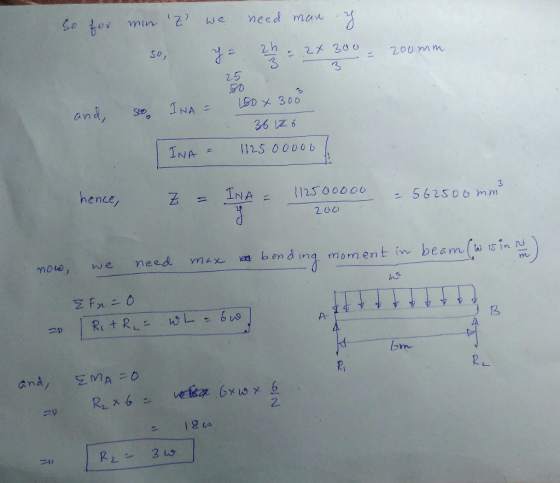
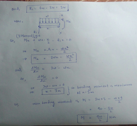
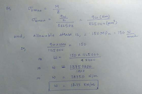
Add Answer to:
The beam has the triangular cross section shown. The allowable stress in bending is 150 MPa....
1. Consider a simply-supported beam with a triangular cross section (Fig. 1). If the allowable bending...
 1. Consider a simply-supported beam with a triangular cross section (Fig. 1). If the allowable bending stress is oallow = 150 MPa, determine the maximum intensity w of the uniformly distributed load. Draw the corresponding shear force and bending moment diagrams В 6m 300 mm 1bh 150 mm Triangular area (a) (b) Figure 1 10 points =15°C, the gap between 2. Fig. 2 shows two cylindrical rod segments fixed to the rigid walls. At To them is 0.25 mm. Each...
The beam having a cross-section as shown is subjected to the distributed load w (1) Calculate...
 The beam having a cross-section as shown is subjected to the distributed load w (1) Calculate the moment of inertia, I (2) If the allowable maximum normal stress ơmax-20 MPa, determine the largest distributed load 5. w. (3) If w 1.5 kN/m, determine the maximum bending stress in the beam. Sketch the stress distribution acting over the cross-section. 100 mm 50mm 120 mm 3 m50 mm 3 m
1) The allowable bending strength in A-A cross section is Oallow= 150 MPa. Determine the maximum...
 1) The allowable bending strength in A-A cross section is Oallow= 150 MPa. Determine the maximum load P where it applied to the bar from point E (40 points). Figure 1 D 600 mm a 300 mm 20 mm В. 50 mm 25 mm 25 mm 25 mm A-A cross section
Q4) If the allowable stress is 120 MPa in tension and 150 MPa in compression, determine...
 Q4) If the allowable stress is 120 MPa in tension and 150 MPa in compression, determine the largest +M and -M that can be applied on the beam section shown in Fig. 4. 25 mm 50 mm 125 mm Fig. 4 150 mm
QUESTION 4. For the beam shown in the figure, the maximum allowable bending stress is 180...
 QUESTION 4. For the beam shown in the figure, the maximum allowable bending stress is 180 MPa and the maximum allowable shear stress is 120 MPa. Choose an appropriate Wide Flange Section (W) that can carry the distributed force and the point force safely. 10 kN 8 kN/m C B 4 m 2 m
A rectangular cross section at a location along a beam in bending is
 (a). A rectangular cross section at a location along a beam in bending is acted upon by a bending moment and a shear force. The cross section is \(120 \mathrm{~mm}\) wide, \(300 \mathrm{~mm}\) deep and is orientated such that it is in bending about its major axis of bending. The magnitudes of the bending moment and shear force are \(315 \mathrm{kNm}\) and \(240 \mathrm{kN}\) respectively. Determine the maximum bending and shear stresses on the cross section. Plot the bending and...
The simply-supported beam having I-beam cross-section as shown in figure is to carry a uniformly distributed...
 The simply-supported beam having I-beam cross-section as shown in figure is to carry a uniformly distributed load over its entire 1.2m length. Specify the maximum allowable load if the beam is made from malleable iron, ASTM A220, class 80002. The allowable tensile stress is 164 MPa and allowable compressive stress is 412 MPa. The centroid of the section is located at 35 mm from the bottom and moment of inertia are Ix = 2.66 x 10 mm". (a) Draw loading...
Determine the largest permissible distributed load w for the beam shown, knowing that the allowable normal...
 Determine the largest permissible distributed load w for the beam shown, knowing that the allowable normal stress is +80 MPa in tension and -100 MPa in compression. Round the final answer to one decimal place.) 60 mm t0 20 mm 02 m 0.2 m kN/m The largest permissible distributed load w for the beam shown is
Using an allowable stress of 154 MPa, determine the largest bending moment M that can be...
 Using an allowable stress of 154 MPa, determine the largest bending moment M that can be applied to the wide-flange beam shown. Neglect the effect of fillets. (Round the final answer to one decimal place.) 12 mm 12 mm 200 mm The largest bending moment that can be applied is KN-m.
7.26 Torking stress in either tension or compression is AMS. 92.8 mm x 185.6 mm o MPa. am 3 m long is simply supported at each end and carries a uniformly distributed load of 10 kN/m. The beam...
 7.26
Torking stress in either tension or compression is AMS. 92.8 mm x 185.6 mm o MPa. am 3 m long is simply supported at each end and carries a uniformly distributed load of 10 kN/m. The beam at rectangular cross section, 75 mm x 150 mm. Determine the magnitude and location of the peak bending ress. Also, find the magnitude of the bending stress at a point 25 mm below the upper surface at the section midway betwcen supports....
7.26
Torking stress in either tension or compression is AMS. 92.8 mm x 185.6 mm o MPa. am 3 m long is simply supported at each end and carries a uniformly distributed load of 10 kN/m. The beam at rectangular cross section, 75 mm x 150 mm. Determine the magnitude and location of the peak bending ress. Also, find the magnitude of the bending stress at a point 25 mm below the upper surface at the section midway betwcen supports....
 1. Consider a simply-supported beam with a triangular cross section (Fig. 1). If the allowable bending stress is oallow = 150 MPa, determine the maximum intensity w of the uniformly distributed load. Draw the corresponding shear force and bending moment diagrams В 6m 300 mm 1bh 150 mm Triangular area (a) (b) Figure 1 10 points =15°C, the gap between 2. Fig. 2 shows two cylindrical rod segments fixed to the rigid walls. At To them is 0.25 mm. Each...
 The beam having a cross-section as shown is subjected to the distributed load w (1) Calculate the moment of inertia, I (2) If the allowable maximum normal stress ơmax-20 MPa, determine the largest distributed load 5. w. (3) If w 1.5 kN/m, determine the maximum bending stress in the beam. Sketch the stress distribution acting over the cross-section. 100 mm 50mm 120 mm 3 m50 mm 3 m
 1) The allowable bending strength in A-A cross section is Oallow= 150 MPa. Determine the maximum load P where it applied to the bar from point E (40 points). Figure 1 D 600 mm a 300 mm 20 mm В. 50 mm 25 mm 25 mm 25 mm A-A cross section
 Q4) If the allowable stress is 120 MPa in tension and 150 MPa in compression, determine the largest +M and -M that can be applied on the beam section shown in Fig. 4. 25 mm 50 mm 125 mm Fig. 4 150 mm
 QUESTION 4. For the beam shown in the figure, the maximum allowable bending stress is 180 MPa and the maximum allowable shear stress is 120 MPa. Choose an appropriate Wide Flange Section (W) that can carry the distributed force and the point force safely. 10 kN 8 kN/m C B 4 m 2 m
 The simply-supported beam having I-beam cross-section as shown in figure is to carry a uniformly distributed load over its entire 1.2m length. Specify the maximum allowable load if the beam is made from malleable iron, ASTM A220, class 80002. The allowable tensile stress is 164 MPa and allowable compressive stress is 412 MPa. The centroid of the section is located at 35 mm from the bottom and moment of inertia are Ix = 2.66 x 10 mm". (a) Draw loading...
 Determine the largest permissible distributed load w for the beam shown, knowing that the allowable normal stress is +80 MPa in tension and -100 MPa in compression. Round the final answer to one decimal place.) 60 mm t0 20 mm 02 m 0.2 m kN/m The largest permissible distributed load w for the beam shown is
 Using an allowable stress of 154 MPa, determine the largest bending moment M that can be applied to the wide-flange beam shown. Neglect the effect of fillets. (Round the final answer to one decimal place.) 12 mm 12 mm 200 mm The largest bending moment that can be applied is KN-m.
 7.26
Torking stress in either tension or compression is AMS. 92.8 mm x 185.6 mm o MPa. am 3 m long is simply supported at each end and carries a uniformly distributed load of 10 kN/m. The beam at rectangular cross section, 75 mm x 150 mm. Determine the magnitude and location of the peak bending ress. Also, find the magnitude of the bending stress at a point 25 mm below the upper surface at the section midway betwcen supports....
7.26
Torking stress in either tension or compression is AMS. 92.8 mm x 185.6 mm o MPa. am 3 m long is simply supported at each end and carries a uniformly distributed load of 10 kN/m. The beam at rectangular cross section, 75 mm x 150 mm. Determine the magnitude and location of the peak bending ress. Also, find the magnitude of the bending stress at a point 25 mm below the upper surface at the section midway betwcen supports....
Most questions answered within 3 hours.
-
Where is the error in this code sequence?
String s1 = "Hello";
String s2 = "ello";...
asked 11 months ago -
Financial data for Joel de Paris, Inc., for last year
follow:
Joel de Paris, Inc.
Balance...
asked 11 months ago -
Consider this reaction:
Al2(SO4)3 (aq)+ BaCl3
(aq) Al2Cl6 (aq)- +
3BaSO4(s) . What is the...
asked 11 months ago -
Suppose that Savneet is considering increasing her
recent random sample from 20 car rentals to 40...
asked 11 months ago -
Trucks arrive at an unloading terminal at an average rate of 120
per hour.
Trucks arrive...
asked 11 months ago -
Why are methanol and ethanol completely soluble in water while
octanol is not very little soluble....
asked 11 months ago -
A facilities manager at a university reads in a research report
that the mean amount of...
asked 11 months ago -
When the CuSO4 is rehydrated by adding water to the anhydrous
compound, is this an endothermic...
asked 11 months ago -
A ray of sunlight is passing from diamond into crown glass; the
angle of incidence is...
asked 11 months ago -
A block of mass 0.249 kg is placed on top of a light, vertical
spring of...
asked 11 months ago -
how do the kidneys compensate in the presences of acidosis
a) trigger hyperventilate
b) reserve acid...
asked 11 months ago -
Question 501 pts
The rental rate of capital to the firm increases. Which of the
following...
asked 11 months ago