
Homework Answers
 1. The circuit consists of parallel and
series capacitors. Capacitance is the charge stored divided by the
voltage passing through it. This is give mathematically
as,
1. The circuit consists of parallel and
series capacitors. Capacitance is the charge stored divided by the
voltage passing through it. This is give mathematically
as,

In a series capacitors, the charge and the voltage flowing through the capacitors is the same.
Hence the final Capacitance given by C is

where 1,2,3...n refer to the number of capacitors.
If capacitors are placed parallel the resulting capacitance is given by

This is because the voltage across each of them is the same .
Now we
can simply the circuit with this knowledge. The  and
and  are in series. So using the formula we get the resulting
Capacitance for these two as
are in series. So using the formula we get the resulting
Capacitance for these two as


This
resultant capacitance is now parallel to  . So we can simply add
1. The circuit consists of parallel and series capacitors. Capacitance is the charge stored divided by the voltage passing through it. This is give mathematically as,
C=(Q/V)
In a series capacitors, the charge and the voltage flowing through the capacitors is the same.
Hence the final Capacitance given by C is
where 1,2,3...n refer to the number of capacitors.
If capacitors are placed parallel the resulting capacitance is given by
This is
because the voltage across each of them is the same .Now we can
simply the circuit with this knowledge. The 2micro F and 4 micro F
are in series. So using the formula we get the resulting
Capacitance for these two as
This
resultant capacitance is now parallel to 12 micro F. So we can
simply add them to get 12 micro F +(4/3) micro F =(40/3) micro
Farad
This resultant capacitance is in series with 5 \mu F so we use the
series formula to get

them to
get 
This
resultant capacitance is in series with  so we use the series formula to get

So this is the equivalent final Capacitance of the Circuit.
The voltage is given to be 20 V.
Hence total charge is Q=CV

Refer image for figures.
We use
figure 3 to find charge and voltage across the 
The charge is the same as total charge so by C=(Q/V)
V for
=Q/C1
=800/11x5
=160/11 V =14.55 V
V for the 40/3 micro Farad=Q/C
=(800x3)/(11x40)
=220/3 micro Farad
Now we use Fig 2 to find remaining answers. Since the 12 micor Farad is parallel to (4/3) micro Farad, the voltage across them is the same but the charge for each of them is different. The capacitor with higher Capacitance gets more charge
V=220/3
So charge on (4/3) micro Farad =(4x220)/(3x3)
=(880/9)
Charge on 12 micro Farad=(12x220)/3
=880
Now we use figure 1,
The charge for the 2 and 4 micro Capacitance is the same. Voltage for each is calculated.
Q=880/9
V for 2 micro Farad=(880/9x2)
=(440/9) V
=48.89 V
V for 4 micro Farad=(880/9x4)
=(220/9)
=24.44 V
Hence we found charge and voltage for each.
2. Voltage across a charging capacitor is given by
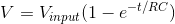
Since charging takes place exponentially and is dependent on R and C
V at input is 200 V so we substitute the values in the question to get
V at 1s for capacitor=200(1-e(-1/10))
=19V
B. Charging current across a capacitor is given by

So upon substitution we get,
I=10-3.e-2/10
=8.187x10⁻⁴ A
c. Voltage across resistor is given by

Voltage across capacitor is give by

We need to find the time when these two are equal,
So 

Putting in the values of R and C we get
t=6.9s
Hence this is the time when the voltage across capacitor is equal to voltage across resistor.
Add Answer to:
1) In the next circuit, the battery has a potential difference of 20 V and it...
This lab involves an animation of an RC circuit. By clicking on the connect battery link...
 This lab involves an animation of an RC circuit. By clicking on
the connect battery link below the animation, you close switch 1
and open switch 2 connecting a 40V battery to the resistor and
capacitor in series. By clicking on the disconnect battery link,
you close switch 2 and open switch 1 eliminating the battery from
the circuit and connecting the resistor and capacitor in series. On
the right hand side a graph of the current vs. time through...
This lab involves an animation of an RC circuit. By clicking on
the connect battery link below the animation, you close switch 1
and open switch 2 connecting a 40V battery to the resistor and
capacitor in series. By clicking on the disconnect battery link,
you close switch 2 and open switch 1 eliminating the battery from
the circuit and connecting the resistor and capacitor in series. On
the right hand side a graph of the current vs. time through...
3. In figure below, the battery has a potential difference of V = 10.0 V and...
 3. In figure below, the battery has a potential difference of V = 10.0 V and the five capacitors each have a capacitance of 10.0 uF. What is the charge on (a) capacitor 1 and (b) capacitor 2?
RC charging circuit Two 0.500-uF capacito 00uF capacitors in series are connected to a 50.0-V battery...
 RC charging circuit Two 0.500-uF capacito 00uF capacitors in series are connected to a 50.0-V battery through a 4.00-M12 stor at r=0 (figure below). The capacitors are initially uncharged. Answer questions 12 and 13. Show all correct governing equations and work for credit. 500 OF (5 points) 12. What is the equivalent capacitance of the circuit? A. 0.500 F B. 0.250 AF C. 1.00uF D. 4.00 uF E. depends on the time since the capacitor is charging (5 points) 3....
ASAP In the figure shown, the battery has potential difference V= 9.0 V, with capacitors of...
 ASAP
In the figure shown, the battery has potential difference V= 9.0 V, with capacitors of capacitance C1 = 12 uF C2- 12 uF, C3 2uF, and Ca 4.0 uF. What is the charge going past the location marked a, after the circuit is turned on?
ASAP
In the figure shown, the battery has potential difference V= 9.0 V, with capacitors of capacitance C1 = 12 uF C2- 12 uF, C3 2uF, and Ca 4.0 uF. What is the charge going past the location marked a, after the circuit is turned on?
An RC circuit consists of a 5 uF capacitor, an 80,000 ohm resistor, and a 12-V...
An RC circuit consists of a 5 uF capacitor, an 80,000 ohm resistor, and a 12-V battery. The switch is closed at t=0. a) Find the time constant of the circuit. b) Find the time to reach 90% of the maximum charge across the capacitor.
The circuit in the figure below contains a 90.0 V battery and four capacitors. In the...
 The circuit in the figure below contains a 90.0 V battery and four capacitors. In the top parallel branch, there are two capacitors, one with a capacitance of C = 1.00 pF and another with a capacitance of 6.00 pF. In the bottom parallel branch, there are two more capacitors, one with a capacitance of 2.00 pF and another with a capacitance of C2 = 3.00 uF. C 6.00 uF 2.00 uF 90.0 V (a) What is the equivalent capacitance...
A 9.0 mu F capacitor is charged by a 9.0 V battery through a resistance R....
 A 9.0 mu F capacitor is charged by a 9.0 V battery through a resistance R. The capacitor reaches a potential difference of 4.00 V at a time 3.00 s after charging begins. Find R. K ohm.
1. Two 50 Ω resistors are in series in a circuit with a 10 V battery....
1. Two 50 Ω resistors are in series in a circuit with a 10 V battery. The change in voltage, in the direction of the current, across either resistor is ___ V. 2. A 40 μF capacitor and a 80 μF capacitor are in series in a circuit with a 10 V battery. The voltage drop, in the direction of the current, across the 40 μF capacitor is ___ V. 3. A 40 μF capacitor and a 100 Ω resistor...
The circuit in the figure below contains a 9.00 v battery and four capacitors. The two...
 The circuit in the figure below contains a 9.00 v battery and four capacitors. The two capacitors on the left and right both have same capacitance of C, -14.20. The capacitors in the top two branches have capacitances of 6.00 pF and C - 28.20 F 6.00 с. 9.00 V (a) What is the equivalent capacitance (in pf) of all the capacitors in the entire circuit? (b) What is the charge (in) stored by each capacitor? right 34.20 pf capacitor...
The figures show a simple RC circuit consisting of a 120.0 V battery in series with...
The figures show a simple RC circuit consisting of a 120.0 V battery in series with a 15.0 μF capacitor and a resistor. Initially, the switch S is open and the capacitor is uncharged. Two seconds after the switch is closed, the voltage across the resistor is 50 V. Q: How much charge is on the capacitor 2.0s after the switch is closed?
 This lab involves an animation of an RC circuit. By clicking on
the connect battery link below the animation, you close switch 1
and open switch 2 connecting a 40V battery to the resistor and
capacitor in series. By clicking on the disconnect battery link,
you close switch 2 and open switch 1 eliminating the battery from
the circuit and connecting the resistor and capacitor in series. On
the right hand side a graph of the current vs. time through...
This lab involves an animation of an RC circuit. By clicking on
the connect battery link below the animation, you close switch 1
and open switch 2 connecting a 40V battery to the resistor and
capacitor in series. By clicking on the disconnect battery link,
you close switch 2 and open switch 1 eliminating the battery from
the circuit and connecting the resistor and capacitor in series. On
the right hand side a graph of the current vs. time through...
 3. In figure below, the battery has a potential difference of V = 10.0 V and the five capacitors each have a capacitance of 10.0 uF. What is the charge on (a) capacitor 1 and (b) capacitor 2?
 RC charging circuit Two 0.500-uF capacito 00uF capacitors in series are connected to a 50.0-V battery through a 4.00-M12 stor at r=0 (figure below). The capacitors are initially uncharged. Answer questions 12 and 13. Show all correct governing equations and work for credit. 500 OF (5 points) 12. What is the equivalent capacitance of the circuit? A. 0.500 F B. 0.250 AF C. 1.00uF D. 4.00 uF E. depends on the time since the capacitor is charging (5 points) 3....
 ASAP
In the figure shown, the battery has potential difference V= 9.0 V, with capacitors of capacitance C1 = 12 uF C2- 12 uF, C3 2uF, and Ca 4.0 uF. What is the charge going past the location marked a, after the circuit is turned on?
ASAP
In the figure shown, the battery has potential difference V= 9.0 V, with capacitors of capacitance C1 = 12 uF C2- 12 uF, C3 2uF, and Ca 4.0 uF. What is the charge going past the location marked a, after the circuit is turned on?
 The circuit in the figure below contains a 90.0 V battery and four capacitors. In the top parallel branch, there are two capacitors, one with a capacitance of C = 1.00 pF and another with a capacitance of 6.00 pF. In the bottom parallel branch, there are two more capacitors, one with a capacitance of 2.00 pF and another with a capacitance of C2 = 3.00 uF. C 6.00 uF 2.00 uF 90.0 V (a) What is the equivalent capacitance...
 A 9.0 mu F capacitor is charged by a 9.0 V battery through a resistance R. The capacitor reaches a potential difference of 4.00 V at a time 3.00 s after charging begins. Find R. K ohm.
 The circuit in the figure below contains a 9.00 v battery and four capacitors. The two capacitors on the left and right both have same capacitance of C, -14.20. The capacitors in the top two branches have capacitances of 6.00 pF and C - 28.20 F 6.00 с. 9.00 V (a) What is the equivalent capacitance (in pf) of all the capacitors in the entire circuit? (b) What is the charge (in) stored by each capacitor? right 34.20 pf capacitor...
Most questions answered within 3 hours.
-
Where is the error in this code sequence?
String s1 = "Hello";
String s2 = "ello";...
asked 10 months ago -
Financial data for Joel de Paris, Inc., for last year
follow:
Joel de Paris, Inc.
Balance...
asked 10 months ago -
Consider this reaction:
Al2(SO4)3 (aq)+ BaCl3
(aq) Al2Cl6 (aq)- +
3BaSO4(s) . What is the...
asked 10 months ago -
Suppose that Savneet is considering increasing her
recent random sample from 20 car rentals to 40...
asked 10 months ago -
Trucks arrive at an unloading terminal at an average rate of 120
per hour.
Trucks arrive...
asked 10 months ago -
Why are methanol and ethanol completely soluble in water while
octanol is not very little soluble....
asked 10 months ago -
A facilities manager at a university reads in a research report
that the mean amount of...
asked 10 months ago -
When the CuSO4 is rehydrated by adding water to the anhydrous
compound, is this an endothermic...
asked 10 months ago -
A ray of sunlight is passing from diamond into crown glass; the
angle of incidence is...
asked 10 months ago -
A block of mass 0.249 kg is placed on top of a light, vertical
spring of...
asked 10 months ago -
how do the kidneys compensate in the presences of acidosis
a) trigger hyperventilate
b) reserve acid...
asked 10 months ago -
Question 501 pts
The rental rate of capital to the firm increases. Which of the
following...
asked 10 months ago