
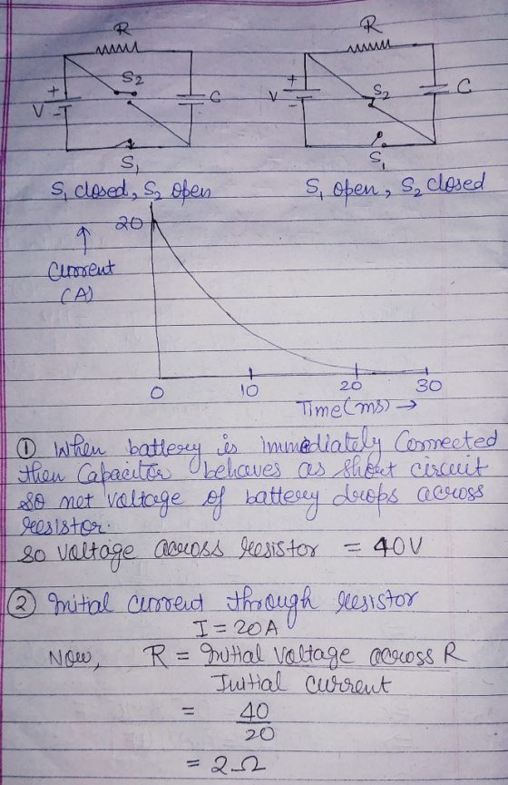
This lab involves an animation of an RC circuit. By clicking on the connect battery link below the animation, you close switch 1 and open switch 2 connecting a 40V battery to the resistor and capacitor in series. By clicking on the disconnect battery link, you close switch 2 and open switch 1 eliminating the battery from the circuit and connecting the resistor and capacitor in series. On the right hand side a graph of the current vs. time through the resistor is shown.
1) Immediately after the battery is connected, what is the
voltage across the resistor?
0 V
10 V
20 V
30 V
40 V
2) What is the resistance of the resistor?
1 ohm
2 ohms
3 ohms
4 ohms
3) After the battery has been connected for a long time, what is
the voltage across the capacitor?
0 V
10 V
20 V
30 V
40 V
4) Immediately after the battery is disconnected, what is the
voltage across the resistor? Explain.
0 V
10 V
20 V
30 V
40 V
5) Immediately after the battery is disconnected, what is the
voltage across the capacitor? Explain.
0 V
10 V
20 V
30 V
40 V
6) After the battery has been disconnected for a long time, what
is the voltage across the resistor? Explain.
0 V
10 V
20 V
30 V
40 V
Homework Answers

Add Answer to:
This lab involves an animation of an RC circuit. By clicking on
the connect battery link...
"O OHLEI E PICS! 3. An RC-Circuit is made up of a 12 kO resistor, a...
 "O OHLEI E PICS! 3. An RC-Circuit is made up of a 12 kO resistor, a 40 uF capacitor and a 9.0 V battery. The battery is used to charge the capacitor, and then it is removed from the circuit through the use of a switch, allowing the capacitor to discharge. a. (3 pts.) What is the time constant of the circuit? b. 17 pts.) Calculate the voltage across the capacitor, voltage across the resistor, and the current in the...
The figures show a simple RC circuit consisting of a 120.0 V battery in series with...
The figures show a simple RC circuit consisting of a 120.0 V battery in series with a 15.0 μF capacitor and a resistor. Initially, the switch S is open and the capacitor is uncharged. Two seconds after the switch is closed, the voltage across the resistor is 50 V. Q: How much charge is on the capacitor 2.0s after the switch is closed?
1. Two 50 Ω resistors are in series in a circuit with a 10 V battery....
1. Two 50 Ω resistors are in series in a circuit with a 10 V battery. The change in voltage, in the direction of the current, across either resistor is ___ V. 2. A 40 μF capacitor and a 80 μF capacitor are in series in a circuit with a 10 V battery. The voltage drop, in the direction of the current, across the 40 μF capacitor is ___ V. 3. A 40 μF capacitor and a 100 Ω resistor...
You connect a battery, resistor, and capacitor as in (Figure 1) , where E = 56.0...
 You connect a battery, resistor, and capacitor as in (Figure 1)
, where
E = 56.0 V , C = 5.00 μF , and R =
130 Ω . The switch S is closed at t = 0.
(A) When the voltage across the capacitor is 8.00 V, what is the
magnitude of the current in the circuit?
(B) At what time t after the switch is closed is the
voltage across the capacitor 8.00 V?
(C) When the voltage...
You connect a battery, resistor, and capacitor as in (Figure 1)
, where
E = 56.0 V , C = 5.00 μF , and R =
130 Ω . The switch S is closed at t = 0.
(A) When the voltage across the capacitor is 8.00 V, what is the
magnitude of the current in the circuit?
(B) At what time t after the switch is closed is the
voltage across the capacitor 8.00 V?
(C) When the voltage...
Construct a RC circuit (series) with a capacitor, a resistor, a battery,
 Part A Charging of RC Circuit 1) Construct a RC circuit (series) with a capacitor, a resistor, a battery, two switches, and appropriate meters that will enable you to make measurements of the parameters for charging up the capacitor. The placement of the switches allows you to measure both charging and discharging of the RC circuit. See diagram below: 2) Choose a combination of Rand C that will give you a time constant(T) of 20 seconds. T=R*C 20= 100* C=0.2F 3) Set the...
1. Two 50 Ω resistors are in series in a circuit with a 10 V battery....
1. Two 50 Ω resistors are in series in a circuit with a 10 V battery. The change in voltage, in the direction of the current, across either resistor is ___ V. Hint: Can you see why the voltage drop in the direction of the current is negative? 2. A 40 μF capacitor and a 80 μF capacitor are in series in a circuit with a 10 V battery. The voltage drop, in the direction of the current, across the...
An RC circuit, hooked up to a battery as shown in the figure, starts with an...
 An RC circuit, hooked up to a battery as shown in the figure,
starts with an uncharged capacitor. The resistance in the circuit
is R = 855.0 ? the capacitor has capacitance of C = 57.0 ?F and the
battery maintains the emf of ? = 26.0 V. The switch is closed at
time t = 0.0 s and the capacitor begins to charge.
a) What is the time constant for this circuit?
4.874×10⁻² s (IS CORRECT)
b) What is...
An RC circuit, hooked up to a battery as shown in the figure,
starts with an uncharged capacitor. The resistance in the circuit
is R = 855.0 ? the capacitor has capacitance of C = 57.0 ?F and the
battery maintains the emf of ? = 26.0 V. The switch is closed at
time t = 0.0 s and the capacitor begins to charge.
a) What is the time constant for this circuit?
4.874×10⁻² s (IS CORRECT)
b) What is...
You connect a battery, resistor and capacitor as in (Figure 1), where epsilon = 31.0 V,...
 You connect a battery, resistor and capacitor as in (Figure 1), where epsilon = 31.0 V, C = 5.00 mu F, and R = 130 Ohm. The switch S is closed at t = 0. When the voltage across the capacitor is 8.00 V, what is the magnitude of the current in the circuit? Express your answer with the appropriate units. At what time t after the switch is closed is the voltage across the capacitor 8.00 V? Express your...
PLEASE ANSWER VERY QUICKLY!! I RATE HIGH!! The experiment is on RC circuits and the aim is to determine the time constant. Your group sets up the circuit with a resistor R and a capacitor C conne...
 PLEASE ANSWER VERY QUICKLY!! I RATE HIGH!!
The experiment is on RC circuits and the aim is to determine the time constant. Your group sets up the circuit with a resistor R and a capacitor C connected to a switch and an ideal battery (E). The circuit diagram is shown in the figure. You close the switch at time Os and the voltage across the capacitor Ve and current I in the ammeter are recorded in a spreadsheet using a...
PLEASE ANSWER VERY QUICKLY!! I RATE HIGH!!
The experiment is on RC circuits and the aim is to determine the time constant. Your group sets up the circuit with a resistor R and a capacitor C connected to a switch and an ideal battery (E). The circuit diagram is shown in the figure. You close the switch at time Os and the voltage across the capacitor Ve and current I in the ammeter are recorded in a spreadsheet using a...
2. (10 pts) Calculate the current through the 4 ohm resistor in the circuit if points...
 2. (10 pts) Calculate the current through the 4 ohm resistor in the circuit if points (a) and (b) connect to a 12 Volt battery 24 3. (10 pts) Same setup as number 2. Caleulate the voltage across the 24 ohm resistor. 4. (10 pts) We have a series RC circuit. (Rİ 200 ohan, cis 50microfrads. The capacitor is initially uncharged when the switch is closed connecting a 12 Volt battery. Caleulate the voltage across the capacitor after 20 milliseconds....
 "O OHLEI E PICS! 3. An RC-Circuit is made up of a 12 kO resistor, a 40 uF capacitor and a 9.0 V battery. The battery is used to charge the capacitor, and then it is removed from the circuit through the use of a switch, allowing the capacitor to discharge. a. (3 pts.) What is the time constant of the circuit? b. 17 pts.) Calculate the voltage across the capacitor, voltage across the resistor, and the current in the...
 You connect a battery, resistor, and capacitor as in (Figure 1)
, where
E = 56.0 V , C = 5.00 μF , and R =
130 Ω . The switch S is closed at t = 0.
(A) When the voltage across the capacitor is 8.00 V, what is the
magnitude of the current in the circuit?
(B) At what time t after the switch is closed is the
voltage across the capacitor 8.00 V?
(C) When the voltage...
You connect a battery, resistor, and capacitor as in (Figure 1)
, where
E = 56.0 V , C = 5.00 μF , and R =
130 Ω . The switch S is closed at t = 0.
(A) When the voltage across the capacitor is 8.00 V, what is the
magnitude of the current in the circuit?
(B) At what time t after the switch is closed is the
voltage across the capacitor 8.00 V?
(C) When the voltage...
 Part A Charging of RC Circuit 1) Construct a RC circuit (series) with a capacitor, a resistor, a battery, two switches, and appropriate meters that will enable you to make measurements of the parameters for charging up the capacitor. The placement of the switches allows you to measure both charging and discharging of the RC circuit. See diagram below: 2) Choose a combination of Rand C that will give you a time constant(T) of 20 seconds. T=R*C 20= 100* C=0.2F 3) Set the...
 An RC circuit, hooked up to a battery as shown in the figure,
starts with an uncharged capacitor. The resistance in the circuit
is R = 855.0 ? the capacitor has capacitance of C = 57.0 ?F and the
battery maintains the emf of ? = 26.0 V. The switch is closed at
time t = 0.0 s and the capacitor begins to charge.
a) What is the time constant for this circuit?
4.874×10⁻² s (IS CORRECT)
b) What is...
An RC circuit, hooked up to a battery as shown in the figure,
starts with an uncharged capacitor. The resistance in the circuit
is R = 855.0 ? the capacitor has capacitance of C = 57.0 ?F and the
battery maintains the emf of ? = 26.0 V. The switch is closed at
time t = 0.0 s and the capacitor begins to charge.
a) What is the time constant for this circuit?
4.874×10⁻² s (IS CORRECT)
b) What is...
 You connect a battery, resistor and capacitor as in (Figure 1), where epsilon = 31.0 V, C = 5.00 mu F, and R = 130 Ohm. The switch S is closed at t = 0. When the voltage across the capacitor is 8.00 V, what is the magnitude of the current in the circuit? Express your answer with the appropriate units. At what time t after the switch is closed is the voltage across the capacitor 8.00 V? Express your...
 PLEASE ANSWER VERY QUICKLY!! I RATE HIGH!!
The experiment is on RC circuits and the aim is to determine the time constant. Your group sets up the circuit with a resistor R and a capacitor C connected to a switch and an ideal battery (E). The circuit diagram is shown in the figure. You close the switch at time Os and the voltage across the capacitor Ve and current I in the ammeter are recorded in a spreadsheet using a...
PLEASE ANSWER VERY QUICKLY!! I RATE HIGH!!
The experiment is on RC circuits and the aim is to determine the time constant. Your group sets up the circuit with a resistor R and a capacitor C connected to a switch and an ideal battery (E). The circuit diagram is shown in the figure. You close the switch at time Os and the voltage across the capacitor Ve and current I in the ammeter are recorded in a spreadsheet using a...
 2. (10 pts) Calculate the current through the 4 ohm resistor in the circuit if points (a) and (b) connect to a 12 Volt battery 24 3. (10 pts) Same setup as number 2. Caleulate the voltage across the 24 ohm resistor. 4. (10 pts) We have a series RC circuit. (Rİ 200 ohan, cis 50microfrads. The capacitor is initially uncharged when the switch is closed connecting a 12 Volt battery. Caleulate the voltage across the capacitor after 20 milliseconds....
Most questions answered within 3 hours.
-
Where is the error in this code sequence?
String s1 = "Hello";
String s2 = "ello";...
asked 10 months ago -
Financial data for Joel de Paris, Inc., for last year
follow:
Joel de Paris, Inc.
Balance...
asked 10 months ago -
Consider this reaction:
Al2(SO4)3 (aq)+ BaCl3
(aq) Al2Cl6 (aq)- +
3BaSO4(s) . What is the...
asked 10 months ago -
Suppose that Savneet is considering increasing her
recent random sample from 20 car rentals to 40...
asked 10 months ago -
Trucks arrive at an unloading terminal at an average rate of 120
per hour.
Trucks arrive...
asked 10 months ago -
Why are methanol and ethanol completely soluble in water while
octanol is not very little soluble....
asked 10 months ago -
A facilities manager at a university reads in a research report
that the mean amount of...
asked 10 months ago -
When the CuSO4 is rehydrated by adding water to the anhydrous
compound, is this an endothermic...
asked 10 months ago -
A ray of sunlight is passing from diamond into crown glass; the
angle of incidence is...
asked 10 months ago -
A block of mass 0.249 kg is placed on top of a light, vertical
spring of...
asked 10 months ago -
how do the kidneys compensate in the presences of acidosis
a) trigger hyperventilate
b) reserve acid...
asked 10 months ago -
Question 501 pts
The rental rate of capital to the firm increases. Which of the
following...
asked 10 months ago