

Homework Answers
PLEASE RATE IT UP!!! THANKS!!!

Add Answer to:
1. Find the following quantities based on the experimental data. @t=0 (just after the switch is...
find response of the parallel RLC circuit on Figure 3. Sketch iL(t) for tE( 0, 50us)...
 find response of the parallel RLC circuit on Figure 3. Sketch iL(t)
for tE( 0, 50us)
initial voltage on the capacitor Vo = 10v.
initial current in the inductor is 100mA.
current source is 100mA.
(Please order all steps so I know how to approach a problem
like this)
Find response of the Parallel RLC circuit on Figure 3. Sketch iz(t) fort € (0, 50uS) Initial Voltage on the capacitor Vo=10V Initial curent in the inductor is 100mA Current Source...
find response of the parallel RLC circuit on Figure 3. Sketch iL(t)
for tE( 0, 50us)
initial voltage on the capacitor Vo = 10v.
initial current in the inductor is 100mA.
current source is 100mA.
(Please order all steps so I know how to approach a problem
like this)
Find response of the Parallel RLC circuit on Figure 3. Sketch iz(t) fort € (0, 50uS) Initial Voltage on the capacitor Vo=10V Initial curent in the inductor is 100mA Current Source...
(2) Q: What can you do to make a parallel-plate capacitor larger? There are several things....
 (2) Q: What can you do to make a parallel-plate capacitor larger? There are several things. Describe as many as you can. In the RC circuit to the right, the capacitor C has a value of 10 uF and the resistor is 144 k 2. The battery has an EMF of 16 V. The circuit is assembled with capacitor is uncharged. At t = 0 s terminal A is connected to terminal B, causing the battery to charge the capacitor....
(1) Consider the RC circuit shown in Figure 1. For t<0 the switch is open, and...
 (1) Consider the RC circuit shown in Figure 1. For t<0 the switch is open, and the charge stored on the capacitor is 0. At t-0 the switch is closed, and the voltage source begins charging the capacitor. Let R1-R2-220 Ω , C-0.47 μ F , Vs-5 V. (a) Write the differential equation as an expression for the capacitor voltage fort> 0 (i.e. write the differential equation) and calculate the time constant (b) Calculate the steady-state capacitor voltage R2 R1...
In this RC circuit, at t = 0 second, switch 1 is closed, switch 2 is...
 In this RC circuit, at t = 0 second, switch 1 is closed, switch
2 is left opened.
a. Determine the current through the uncharged capacitor and the
2 resistors at t = 0 second. (1.33 A)
b. Determine the current through the capacitor and the 2
resistors at t = 100 µs. (0.35 A)
c. For this part, switch 1 is left opened and switch 2 is closed
after the capacitor was charged for a very long time (assume...
In this RC circuit, at t = 0 second, switch 1 is closed, switch
2 is left opened.
a. Determine the current through the uncharged capacitor and the
2 resistors at t = 0 second. (1.33 A)
b. Determine the current through the capacitor and the 2
resistors at t = 100 µs. (0.35 A)
c. For this part, switch 1 is left opened and switch 2 is closed
after the capacitor was charged for a very long time (assume...
just do question 26 and 30 and show all your work (a) Select R so that 26. For the cincuit of Fig. 943,.40 30u-) m v...
 just do question 26 and 30 and show all your work
(a) Select R so that 26. For the cincuit of Fig. 943,.40 30u-) m v(0+) 6 V. (b) Compute (2 ms). (c) Determine the settling time of the capacitor voltage. (d) Is the inductor current settling time the same as your answer to part (c)? 27. The current source in Fig. 9.43 is id) = 101(1-1) μ A. (a) Select Ri such that iLO")-2 μΑ. Compute L at t-500...
just do question 26 and 30 and show all your work
(a) Select R so that 26. For the cincuit of Fig. 943,.40 30u-) m v(0+) 6 V. (b) Compute (2 ms). (c) Determine the settling time of the capacitor voltage. (d) Is the inductor current settling time the same as your answer to part (c)? 27. The current source in Fig. 9.43 is id) = 101(1-1) μ A. (a) Select Ri such that iLO")-2 μΑ. Compute L at t-500...
Just part d. T o WC SWITCH RC-6 At t=0 the capacitor is uncharged and the...
 Just part d.
T o WC SWITCH RC-6 At t=0 the capacitor is uncharged and the switch is closed in the circuit shown below. The emf is 12.0V and the resistors are Ri=10.092 and R2=20.092. The capacitor is 0.250f. switch a) Find the current thru R, at t=0 (the instant after the switch is closed). R=10.00 Think carefully before starting any calculations. e=12.0V b) Find the current thru R, a long time! after the switch is closed. c) Find the...
Just part d.
T o WC SWITCH RC-6 At t=0 the capacitor is uncharged and the switch is closed in the circuit shown below. The emf is 12.0V and the resistors are Ri=10.092 and R2=20.092. The capacitor is 0.250f. switch a) Find the current thru R, at t=0 (the instant after the switch is closed). R=10.00 Think carefully before starting any calculations. e=12.0V b) Find the current thru R, a long time! after the switch is closed. c) Find the...
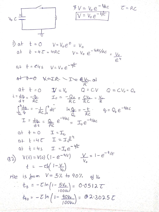
1. A capacitor C has been charged up to potential Vo. At timet0, it is connected...
 1. A capacitor C has been charged up to potential Vo. At timet0, it is connected to a resistor R, and begins to discharge [see figure (a) below] +0 (a) i Determine the charge Q(t) on the capacitor as a function of time. ii. What is the current I(t) through the resistor? iii. Sketch Q(t) and I(t) as a function oft iv. Wha v. By integrating P VI, where P is the power delivered to the circuit and V the...
At time t-0, an RC circuit consists of a 16.5-V emf device, a 68.0-Q resistor, and...
 At time t-0, an RC circuit consists of a 16.5-V emf device, a 68.0-Q resistor, and a 152.0-pF capacitor that is fully charged. The switch is thrown so that the capacitor begins to discharge (a) what is the time constant τ of this circuit? 1.1e-2 Your response is within 10% of the correct value. This may be due to roundoff error, or you could have a mistake in your calculation. Carry out all intermediate results to at least four-digit accuracy...
Learning Goal: To analyze an RC circuit to determine the initial voltage across a capacitor, the...
 Learning Goal: To analyze an RC circuit to determine the initial voltage across a capacitor, the time constant, and the expression for the natural response of the capacitor voltage, and then to find other circuit quantities such as current,voltage, power, or energy. The natural response of an RC circuit is the response of the capacitor voltage to the sudden removal of a DC source. When this occurs, the capacitor releases its stored energy Figure < 10121〉 t 0 V. Figure...
Figure 1 shows a circuit after some switch-flipping and is now at time t = 0....
 Figure 1 shows a circuit after some switch-flipping and is now at time t = 0. It contains a capacitor that was charged to v.(0") = 75 V and an inductor that was charged to i (0°) = 3 A. 10) Is this circuit overdamped, underdamped, or critically damped [2 points A) Is this circuit displaying a natural or step response? (2 points) Solve for y(t) fort > 0 [8 points) +35w 13.230.išao Ous. "
 find response of the parallel RLC circuit on Figure 3. Sketch iL(t)
for tE( 0, 50us)
initial voltage on the capacitor Vo = 10v.
initial current in the inductor is 100mA.
current source is 100mA.
(Please order all steps so I know how to approach a problem
like this)
Find response of the Parallel RLC circuit on Figure 3. Sketch iz(t) fort € (0, 50uS) Initial Voltage on the capacitor Vo=10V Initial curent in the inductor is 100mA Current Source...
find response of the parallel RLC circuit on Figure 3. Sketch iL(t)
for tE( 0, 50us)
initial voltage on the capacitor Vo = 10v.
initial current in the inductor is 100mA.
current source is 100mA.
(Please order all steps so I know how to approach a problem
like this)
Find response of the Parallel RLC circuit on Figure 3. Sketch iz(t) fort € (0, 50uS) Initial Voltage on the capacitor Vo=10V Initial curent in the inductor is 100mA Current Source...
 (2) Q: What can you do to make a parallel-plate capacitor larger? There are several things. Describe as many as you can. In the RC circuit to the right, the capacitor C has a value of 10 uF and the resistor is 144 k 2. The battery has an EMF of 16 V. The circuit is assembled with capacitor is uncharged. At t = 0 s terminal A is connected to terminal B, causing the battery to charge the capacitor....
 (1) Consider the RC circuit shown in Figure 1. For t<0 the switch is open, and the charge stored on the capacitor is 0. At t-0 the switch is closed, and the voltage source begins charging the capacitor. Let R1-R2-220 Ω , C-0.47 μ F , Vs-5 V. (a) Write the differential equation as an expression for the capacitor voltage fort> 0 (i.e. write the differential equation) and calculate the time constant (b) Calculate the steady-state capacitor voltage R2 R1...
 In this RC circuit, at t = 0 second, switch 1 is closed, switch
2 is left opened.
a. Determine the current through the uncharged capacitor and the
2 resistors at t = 0 second. (1.33 A)
b. Determine the current through the capacitor and the 2
resistors at t = 100 µs. (0.35 A)
c. For this part, switch 1 is left opened and switch 2 is closed
after the capacitor was charged for a very long time (assume...
In this RC circuit, at t = 0 second, switch 1 is closed, switch
2 is left opened.
a. Determine the current through the uncharged capacitor and the
2 resistors at t = 0 second. (1.33 A)
b. Determine the current through the capacitor and the 2
resistors at t = 100 µs. (0.35 A)
c. For this part, switch 1 is left opened and switch 2 is closed
after the capacitor was charged for a very long time (assume...
 just do question 26 and 30 and show all your work
(a) Select R so that 26. For the cincuit of Fig. 943,.40 30u-) m v(0+) 6 V. (b) Compute (2 ms). (c) Determine the settling time of the capacitor voltage. (d) Is the inductor current settling time the same as your answer to part (c)? 27. The current source in Fig. 9.43 is id) = 101(1-1) μ A. (a) Select Ri such that iLO")-2 μΑ. Compute L at t-500...
just do question 26 and 30 and show all your work
(a) Select R so that 26. For the cincuit of Fig. 943,.40 30u-) m v(0+) 6 V. (b) Compute (2 ms). (c) Determine the settling time of the capacitor voltage. (d) Is the inductor current settling time the same as your answer to part (c)? 27. The current source in Fig. 9.43 is id) = 101(1-1) μ A. (a) Select Ri such that iLO")-2 μΑ. Compute L at t-500...
 Just part d.
T o WC SWITCH RC-6 At t=0 the capacitor is uncharged and the switch is closed in the circuit shown below. The emf is 12.0V and the resistors are Ri=10.092 and R2=20.092. The capacitor is 0.250f. switch a) Find the current thru R, at t=0 (the instant after the switch is closed). R=10.00 Think carefully before starting any calculations. e=12.0V b) Find the current thru R, a long time! after the switch is closed. c) Find the...
Just part d.
T o WC SWITCH RC-6 At t=0 the capacitor is uncharged and the switch is closed in the circuit shown below. The emf is 12.0V and the resistors are Ri=10.092 and R2=20.092. The capacitor is 0.250f. switch a) Find the current thru R, at t=0 (the instant after the switch is closed). R=10.00 Think carefully before starting any calculations. e=12.0V b) Find the current thru R, a long time! after the switch is closed. c) Find the...
 1. A capacitor C has been charged up to potential Vo. At timet0, it is connected to a resistor R, and begins to discharge [see figure (a) below] +0 (a) i Determine the charge Q(t) on the capacitor as a function of time. ii. What is the current I(t) through the resistor? iii. Sketch Q(t) and I(t) as a function oft iv. Wha v. By integrating P VI, where P is the power delivered to the circuit and V the...
 At time t-0, an RC circuit consists of a 16.5-V emf device, a 68.0-Q resistor, and a 152.0-pF capacitor that is fully charged. The switch is thrown so that the capacitor begins to discharge (a) what is the time constant τ of this circuit? 1.1e-2 Your response is within 10% of the correct value. This may be due to roundoff error, or you could have a mistake in your calculation. Carry out all intermediate results to at least four-digit accuracy...
 Learning Goal: To analyze an RC circuit to determine the initial voltage across a capacitor, the time constant, and the expression for the natural response of the capacitor voltage, and then to find other circuit quantities such as current,voltage, power, or energy. The natural response of an RC circuit is the response of the capacitor voltage to the sudden removal of a DC source. When this occurs, the capacitor releases its stored energy Figure < 10121〉 t 0 V. Figure...
 Figure 1 shows a circuit after some switch-flipping and is now at time t = 0. It contains a capacitor that was charged to v.(0") = 75 V and an inductor that was charged to i (0°) = 3 A. 10) Is this circuit overdamped, underdamped, or critically damped [2 points A) Is this circuit displaying a natural or step response? (2 points) Solve for y(t) fort > 0 [8 points) +35w 13.230.išao Ous. "
Most questions answered within 3 hours.
-
Where is the error in this code sequence?
String s1 = "Hello";
String s2 = "ello";...
asked 10 months ago -
Financial data for Joel de Paris, Inc., for last year
follow:
Joel de Paris, Inc.
Balance...
asked 10 months ago -
Consider this reaction:
Al2(SO4)3 (aq)+ BaCl3
(aq) Al2Cl6 (aq)- +
3BaSO4(s) . What is the...
asked 10 months ago -
Suppose that Savneet is considering increasing her
recent random sample from 20 car rentals to 40...
asked 10 months ago -
Trucks arrive at an unloading terminal at an average rate of 120
per hour.
Trucks arrive...
asked 10 months ago -
Why are methanol and ethanol completely soluble in water while
octanol is not very little soluble....
asked 10 months ago -
A facilities manager at a university reads in a research report
that the mean amount of...
asked 10 months ago -
When the CuSO4 is rehydrated by adding water to the anhydrous
compound, is this an endothermic...
asked 10 months ago -
A ray of sunlight is passing from diamond into crown glass; the
angle of incidence is...
asked 10 months ago -
A block of mass 0.249 kg is placed on top of a light, vertical
spring of...
asked 10 months ago -
how do the kidneys compensate in the presences of acidosis
a) trigger hyperventilate
b) reserve acid...
asked 10 months ago -
Question 501 pts
The rental rate of capital to the firm increases. Which of the
following...
asked 10 months ago