
Consider a drive shaft design concept as shown in the accompanying figure.
Homework Answers
Given

a)Take  as tangential force on gear
In the drive shaft design the torque is transfered at gear and belt drive
Torque transfered by the shaft based on belt drive tension

Torque equation with respect to z-axis

The gear force

b)
The radial gear force

Loading x-z plane
Take moment balance about O in y direction


Take force balance in x direction

Shear force diagram

Bending diagram

c)Loading in y-z plane

Take Moment balance about O in x direction
Taking force balance in y direction
Shear diagram

Bending diagram

d)
Resultant bending moment can be calaculated as square root of sum of square bending moment in y and x direction
At A

At B

Maximum bending momen is at B
Maximum Bending stress in the shaft

Factor of safety for bending against yielding in bending

d)
Torque diagram

Maximum torque is between gear and belt drive
Maximum Torsional shear

Factor of safety against yielding in torsion

Add Answer to:
Consider a drive shaft design concept as shown in the
accompanying figure.
Consider a drive shaft...
The shaft in the figure below is supported on journal bearings that do not offer any resistance t...
 The shaft in the figure below is supported on journal bearings that do not offer any resistance to axial load. The yield strength of the material is Ơ,-300 MPa and the safety factor is FS-2.5 1) 2) 3) 4) Determine the reaction at the supports. Draw the shear force, bending and torsion moment diagrams Derive an expression for the components of the stress tensor at a cross section of the shaft Neglect the shear stress due to the transverse shear...
The figure above shows a shaft mounted in bearings A and D and having pulleys at B and C.
 The figure above shows a shaft mounted in bearings A and D and having pulleys at B and C. The shaft is 20 mm in diameter and made of AISI 1020 CD steel. The forces shown acting on the pulley surfaces represent the belt tensions. The shaft is concerned with yielding and fatigue failure. [Stress analysis) (1) Draw the free body diagrams and find reaction forces at A and D in the xy and xz planes. (2) Draw the shear force and moment...
A countershaft carrying two V-belt pulleys is shown in the figure. Pulley A receives power from...
 A countershaft carrying two V-belt pulleys is shown in the
figure. Pulley A receives power from a motor through a belt with
the belt tensions shown. The power is transmitted through the shaft
and delivered to the belt on pulley B. Assume the belt tension on
the loose side at B is 15 percent of the tension on the tight side.
Yield of the Shaft ?? = 560 ???
a) Determine the tensions in the belt on pulley B, assuming...
A countershaft carrying two V-belt pulleys is shown in the
figure. Pulley A receives power from a motor through a belt with
the belt tensions shown. The power is transmitted through the shaft
and delivered to the belt on pulley B. Assume the belt tension on
the loose side at B is 15 percent of the tension on the tight side.
Yield of the Shaft ?? = 560 ???
a) Determine the tensions in the belt on pulley B, assuming...
please solve with details Question#1140Marksl The shaft shown in the figure is rotating at 650 rpm and it receives 5592.75 W through a flexible coupling at its right end. The power is delivered t...
 please solve with details
Question#1140Marksl The shaft shown in the figure is rotating at 650 rpm and it receives 5592.75 W through a flexible coupling at its right end. The power is delivered to an adjacent shaft through a single helical gear B having a normal pressure angle of 20° and a helix angle of 15o. The pitch diameter for the gear is 105.1814 mm (4.141 in). A spacer is used to position the gear relative to bearing C. The...
please solve with details
Question#1140Marksl The shaft shown in the figure is rotating at 650 rpm and it receives 5592.75 W through a flexible coupling at its right end. The power is delivered to an adjacent shaft through a single helical gear B having a normal pressure angle of 20° and a helix angle of 15o. The pitch diameter for the gear is 105.1814 mm (4.141 in). A spacer is used to position the gear relative to bearing C. The...
3- The shaft shown in the figure rotates with constant angular velocity and is transmitting a...
 3- The shaft shown in the figure rotates with constant angular velocity and is transmitting a torque from gear B to gear C through the forces Exo and Ez as shown. The shaft is subject to combined bending and torsion due to the forces shown. The weights of the shaft and pulleys may be neglected and the supports can exert only concentrated force reactions. The radius of the gear at B is 50 mm and that at C is 75...
Solve in SI units. A gear reduction unit uses the countershaft shown in the figure. Gear...
 Solve in SI units.
A gear reduction unit uses the countershaft shown in the figure.
Gear A receives power from another gear with the transmitted force
FA applied at the 20ᵒ pressure angle as shown. The power is
transmitted through the shaft and delivered through gear B through
a transmitted force FB at the pressure angle shown. a) Determine
the force FB, assuming the shaft is running at a constant speed. b)
Find the magnitudes of the bearing reaction forces,...
Solve in SI units.
A gear reduction unit uses the countershaft shown in the figure.
Gear A receives power from another gear with the transmitted force
FA applied at the 20ᵒ pressure angle as shown. The power is
transmitted through the shaft and delivered through gear B through
a transmitted force FB at the pressure angle shown. a) Determine
the force FB, assuming the shaft is running at a constant speed. b)
Find the magnitudes of the bearing reaction forces,...
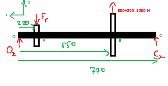
The shaft is supported by smooth journal bearings at A and B that only exert vertical reactions on the shaft.
 The shaft is supported by smooth journal bearings at A and B that only exert vertical reactions on the shaft. a) Calculate the reaction forces at the supports. b) Draw the shear force ve bending moment diagrams. c) Ifd-90 mm, the absolute maximum bending stress in the beam is equal to....
It is required to design a square key for fixing gear on a shaft of 50 mm diameter. 14 KW power a...
 It is required to design a square key for fixing gear on a shaft of 50 mm diameter. 14 KW power at 317 rps is transmitted from the shaft to the gear. Determine the applied Torque in N-m It is required to design a key for fixing gear on a shaft of 50 mm diameter. It is required that 15 kW power at 720 rpm is to be transmitted from the shaft to the gear. The yield strength of the...
The shaft in the figure below is supported on journal bearings that do not offer any resistance t...
 The shaft in the figure below is supported on journal bearings that do not offer any resistance to axial load. The yield strength of the material is o",-300 MPa and the safety factor is FS-2.5 Derive an expression for the components of the stress tensor at a cross section of the shaft Neglect the shear stress due to the transverse shear forces and determine to the nearest millimeter, the smallest diameter of the shaft that will support the loading strength....
Pulley Diameter = 800 mm Base Plate Diameter = 1200 mm Shaft Mounted Wheel Axial force...
 Pulley Diameter = 800 mm Base Plate Diameter = 1200 mm Shaft Mounted Wheel Axial force F2 along the shaft axis Belt connected to motor with tension force F Figure 1. Side View Belt Bearing A. Bearing B FR = 2 kN --- - - - - - - - - - - > ---- 500 mm 500 mm 500 mm F1 = 500 N 'Fw = 1 kN Figure 2. The design of a fatigue test machine for car...
 The shaft in the figure below is supported on journal bearings that do not offer any resistance to axial load. The yield strength of the material is Ơ,-300 MPa and the safety factor is FS-2.5 1) 2) 3) 4) Determine the reaction at the supports. Draw the shear force, bending and torsion moment diagrams Derive an expression for the components of the stress tensor at a cross section of the shaft Neglect the shear stress due to the transverse shear...
 A countershaft carrying two V-belt pulleys is shown in the
figure. Pulley A receives power from a motor through a belt with
the belt tensions shown. The power is transmitted through the shaft
and delivered to the belt on pulley B. Assume the belt tension on
the loose side at B is 15 percent of the tension on the tight side.
Yield of the Shaft ?? = 560 ???
a) Determine the tensions in the belt on pulley B, assuming...
A countershaft carrying two V-belt pulleys is shown in the
figure. Pulley A receives power from a motor through a belt with
the belt tensions shown. The power is transmitted through the shaft
and delivered to the belt on pulley B. Assume the belt tension on
the loose side at B is 15 percent of the tension on the tight side.
Yield of the Shaft ?? = 560 ???
a) Determine the tensions in the belt on pulley B, assuming...
 please solve with details
Question#1140Marksl The shaft shown in the figure is rotating at 650 rpm and it receives 5592.75 W through a flexible coupling at its right end. The power is delivered to an adjacent shaft through a single helical gear B having a normal pressure angle of 20° and a helix angle of 15o. The pitch diameter for the gear is 105.1814 mm (4.141 in). A spacer is used to position the gear relative to bearing C. The...
please solve with details
Question#1140Marksl The shaft shown in the figure is rotating at 650 rpm and it receives 5592.75 W through a flexible coupling at its right end. The power is delivered to an adjacent shaft through a single helical gear B having a normal pressure angle of 20° and a helix angle of 15o. The pitch diameter for the gear is 105.1814 mm (4.141 in). A spacer is used to position the gear relative to bearing C. The...
 3- The shaft shown in the figure rotates with constant angular velocity and is transmitting a torque from gear B to gear C through the forces Exo and Ez as shown. The shaft is subject to combined bending and torsion due to the forces shown. The weights of the shaft and pulleys may be neglected and the supports can exert only concentrated force reactions. The radius of the gear at B is 50 mm and that at C is 75...
 Solve in SI units.
A gear reduction unit uses the countershaft shown in the figure.
Gear A receives power from another gear with the transmitted force
FA applied at the 20ᵒ pressure angle as shown. The power is
transmitted through the shaft and delivered through gear B through
a transmitted force FB at the pressure angle shown. a) Determine
the force FB, assuming the shaft is running at a constant speed. b)
Find the magnitudes of the bearing reaction forces,...
Solve in SI units.
A gear reduction unit uses the countershaft shown in the figure.
Gear A receives power from another gear with the transmitted force
FA applied at the 20ᵒ pressure angle as shown. The power is
transmitted through the shaft and delivered through gear B through
a transmitted force FB at the pressure angle shown. a) Determine
the force FB, assuming the shaft is running at a constant speed. b)
Find the magnitudes of the bearing reaction forces,...
 It is required to design a square key for fixing gear on a shaft of 50 mm diameter. 14 KW power at 317 rps is transmitted from the shaft to the gear. Determine the applied Torque in N-m It is required to design a key for fixing gear on a shaft of 50 mm diameter. It is required that 15 kW power at 720 rpm is to be transmitted from the shaft to the gear. The yield strength of the...
 The shaft in the figure below is supported on journal bearings that do not offer any resistance to axial load. The yield strength of the material is o",-300 MPa and the safety factor is FS-2.5 Derive an expression for the components of the stress tensor at a cross section of the shaft Neglect the shear stress due to the transverse shear forces and determine to the nearest millimeter, the smallest diameter of the shaft that will support the loading strength....
 Pulley Diameter = 800 mm Base Plate Diameter = 1200 mm Shaft Mounted Wheel Axial force F2 along the shaft axis Belt connected to motor with tension force F Figure 1. Side View Belt Bearing A. Bearing B FR = 2 kN --- - - - - - - - - - - > ---- 500 mm 500 mm 500 mm F1 = 500 N 'Fw = 1 kN Figure 2. The design of a fatigue test machine for car...
Most questions answered within 3 hours.
-
Where is the error in this code sequence?
String s1 = "Hello";
String s2 = "ello";...
asked 10 months ago -
Financial data for Joel de Paris, Inc., for last year
follow:
Joel de Paris, Inc.
Balance...
asked 10 months ago -
Consider this reaction:
Al2(SO4)3 (aq)+ BaCl3
(aq) Al2Cl6 (aq)- +
3BaSO4(s) . What is the...
asked 10 months ago -
Suppose that Savneet is considering increasing her
recent random sample from 20 car rentals to 40...
asked 10 months ago -
Trucks arrive at an unloading terminal at an average rate of 120
per hour.
Trucks arrive...
asked 10 months ago -
Why are methanol and ethanol completely soluble in water while
octanol is not very little soluble....
asked 10 months ago -
A facilities manager at a university reads in a research report
that the mean amount of...
asked 10 months ago -
When the CuSO4 is rehydrated by adding water to the anhydrous
compound, is this an endothermic...
asked 10 months ago -
A ray of sunlight is passing from diamond into crown glass; the
angle of incidence is...
asked 10 months ago -
A block of mass 0.249 kg is placed on top of a light, vertical
spring of...
asked 10 months ago -
how do the kidneys compensate in the presences of acidosis
a) trigger hyperventilate
b) reserve acid...
asked 10 months ago -
Question 501 pts
The rental rate of capital to the firm increases. Which of the
following...
asked 10 months ago