
Homework Answers
dia of shaft according to MSST: 10.87mm
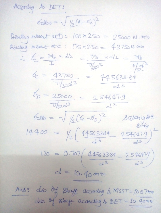
dia of shaft according to DET: 10.40mm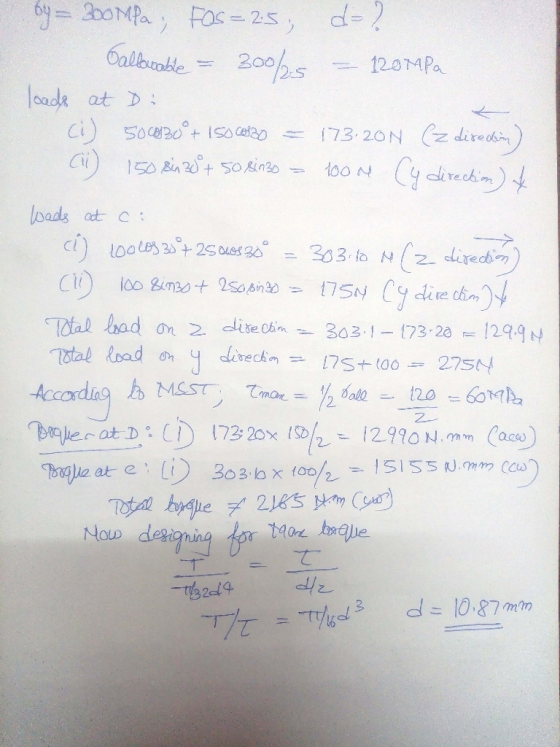
Add Answer to:
The shaft in the figure below is supported on journal bearings that do not offer any resistance t...
The shaft in the figure below is supported on journal bearings that do not offer any resistance t...
 The shaft in the figure below is supported on journal bearings that do not offer any resistance to axial load. The yield strength of the material is Ơ,-300 MPa and the safety factor is FS-2.5 1) 2) 3) 4) Determine the reaction at the supports. Draw the shear force, bending and torsion moment diagrams Derive an expression for the components of the stress tensor at a cross section of the shaft Neglect the shear stress due to the transverse shear...
The shaft shown in the following figure is supported by smooth journal bearings at A and...
 The shaft shown in the following figure is supported by smooth journal bearings at A and B. Due to the transmitted power to and from the shaft, the belts on the pulleys are subjected to the tensions shown. The shaft is made of a material having yield strength is 680 MPa and the shear strength is 520 MPa. Employ a factor of safety of 3. z 150 mm D A 30° 200mm 50 N 130° 100 N 30° 150 N...
Question 2 [Shaft design] (10 Marks) The shaft shown is supported by two smooth journal bearings...
 Question 2 [Shaft design] (10 Marks) The shaft shown is supported by two smooth journal bearings at A and B. Due to the transmission of power to and from the shaft, the belts on the pulleys are subjected to the tensions shown. Determine the smallest diameter of the shaft using the maximum- shear-stress theory, with t,llow = 50 MPa. The radius of the shaft can be obtained 1/3 VM2T2 2 using c JETallow op .0.050 m C 0.250 m ary...
(30 pts) Shaft Yielding. A solid circular shaft with 125 mm diameter rotates in bearings at 30 rad/s. Transverse loadings produce a maximum bending moment of 10 kNm. (For 3. e meaning of transver...
 (30 pts) Shaft Yielding. A solid circular shaft with 125 mm diameter rotates in bearings at 30 rad/s. Transverse loadings produce a maximum bending moment of 10 kNm. (For 3. e meaning of transverse loading see the image below.) Given the tensile yield strength th of the shaft material as 300 MPa, find the power this shaft can transmit according to the Tresca and von Mises yield criteria. Hint: You may need to use Engineer's Theory of Bending (ETB) to...
Determine the required diameter of a steel transmission shaft 10 m in length and of yield...
 Determine the required diameter of a steel transmission shaft 10 m in length and of yield strength 350 MPa in order to resist a torque of up to 500 N-m. The shaft is supported by frictionless bearings at its ends. Design the shaft with a factor of safety of 1.5 according to (a) the maximum shear stress theory and (b) the maximum distortion energy theory
The shaft shown in the figure is supported on bearings located at A and D. The...
 The shaft shown in the figure is supported on bearings located at A and D. The shaft is made from steel with a yield strength of 400 MPa and an ultimate strength of 600 MPa. The shaft has a machined surface finish. The geometric stress concentration at point A, B, C, and D is 1.65. The material has a notch sensitivity of 0.896. All dimensions are in mm. If the shaft rotates, with the force F remaining fixed, find the...
The rotating solid steel shaft is simply supported by bearings at points B and C and is driven by gear (not shown) which meshes with the spur gear at D
 The rotating solid steel shaft is simply supported by bearings at points B and C and is driven by gear (not shown) which meshes with the spur gear at D, which has a 150-mm pitch diameter. The force F from the drive gear acts at a pressure angle of 20". The shaft transmits a torque to point A of TA = 340 N.m. The shaft is machined from steel with Sy= 420 MPa and Sut = 560 MPa. The fatigue...
A shaft with a diameter of 43 mm, is shown below On the right hand side...
 A shaft with a diameter of 43 mm, is shown below On the right
hand side at location D a wheel has a force F of 4824N applied. The
diameter of this wheel is 150 mm. The torque produced by F is
transmitted through the entire shaft to location A where the torque
is reacted. There are no other constraints at location A. Bearings,
are located at B and C, and provide radial constraint. The bearing
at B also provides...
A shaft with a diameter of 43 mm, is shown below On the right
hand side at location D a wheel has a force F of 4824N applied. The
diameter of this wheel is 150 mm. The torque produced by F is
transmitted through the entire shaft to location A where the torque
is reacted. There are no other constraints at location A. Bearings,
are located at B and C, and provide radial constraint. The bearing
at B also provides...
Please answer A and B. The rotating solid stedl shaft is simply supported by bearings at...
 Please answer A and B.
The rotating solid stedl shaft is simply supported by bearings at points B and C and is driven by a gear (not shown) which meshes with the spur gear at D, which has a 150-mm pitch diameter. The force F from the drive gear acts at a pressure angle of 20. The shaft transmits a torque to point A of TA-340 N m. The shaft is machined from steel with Sy- 420 MPa and Sut-560...
Please answer A and B.
The rotating solid stedl shaft is simply supported by bearings at points B and C and is driven by a gear (not shown) which meshes with the spur gear at D, which has a 150-mm pitch diameter. The force F from the drive gear acts at a pressure angle of 20. The shaft transmits a torque to point A of TA-340 N m. The shaft is machined from steel with Sy- 420 MPa and Sut-560...
answer with steps please 4. Figure below shows a rotating shaft simply supported in ball bearings...
 answer with steps please
4. Figure below shows a rotating shaft simply supported in ball bearings at A and D and loaded by a nonrotating force F of 6.8 kN. The shaft is made AISI/SAE cold drawn 1050 steel, estimate the life of the part. 550 C 400 B - 6.8 EN 75 -100 - 250 --- -125 Stress amplitude (MPa) 10 10 10 10 10 Fatigue life cycles) 10
answer with steps please
4. Figure below shows a rotating shaft simply supported in ball bearings at A and D and loaded by a nonrotating force F of 6.8 kN. The shaft is made AISI/SAE cold drawn 1050 steel, estimate the life of the part. 550 C 400 B - 6.8 EN 75 -100 - 250 --- -125 Stress amplitude (MPa) 10 10 10 10 10 Fatigue life cycles) 10
 The shaft in the figure below is supported on journal bearings that do not offer any resistance to axial load. The yield strength of the material is Ơ,-300 MPa and the safety factor is FS-2.5 1) 2) 3) 4) Determine the reaction at the supports. Draw the shear force, bending and torsion moment diagrams Derive an expression for the components of the stress tensor at a cross section of the shaft Neglect the shear stress due to the transverse shear...
 The shaft shown in the following figure is supported by smooth journal bearings at A and B. Due to the transmitted power to and from the shaft, the belts on the pulleys are subjected to the tensions shown. The shaft is made of a material having yield strength is 680 MPa and the shear strength is 520 MPa. Employ a factor of safety of 3. z 150 mm D A 30° 200mm 50 N 130° 100 N 30° 150 N...
 Question 2 [Shaft design] (10 Marks) The shaft shown is supported by two smooth journal bearings at A and B. Due to the transmission of power to and from the shaft, the belts on the pulleys are subjected to the tensions shown. Determine the smallest diameter of the shaft using the maximum- shear-stress theory, with t,llow = 50 MPa. The radius of the shaft can be obtained 1/3 VM2T2 2 using c JETallow op .0.050 m C 0.250 m ary...
 (30 pts) Shaft Yielding. A solid circular shaft with 125 mm diameter rotates in bearings at 30 rad/s. Transverse loadings produce a maximum bending moment of 10 kNm. (For 3. e meaning of transverse loading see the image below.) Given the tensile yield strength th of the shaft material as 300 MPa, find the power this shaft can transmit according to the Tresca and von Mises yield criteria. Hint: You may need to use Engineer's Theory of Bending (ETB) to...
 Determine the required diameter of a steel transmission shaft 10 m in length and of yield strength 350 MPa in order to resist a torque of up to 500 N-m. The shaft is supported by frictionless bearings at its ends. Design the shaft with a factor of safety of 1.5 according to (a) the maximum shear stress theory and (b) the maximum distortion energy theory
 The shaft shown in the figure is supported on bearings located at A and D. The shaft is made from steel with a yield strength of 400 MPa and an ultimate strength of 600 MPa. The shaft has a machined surface finish. The geometric stress concentration at point A, B, C, and D is 1.65. The material has a notch sensitivity of 0.896. All dimensions are in mm. If the shaft rotates, with the force F remaining fixed, find the...
 A shaft with a diameter of 43 mm, is shown below On the right
hand side at location D a wheel has a force F of 4824N applied. The
diameter of this wheel is 150 mm. The torque produced by F is
transmitted through the entire shaft to location A where the torque
is reacted. There are no other constraints at location A. Bearings,
are located at B and C, and provide radial constraint. The bearing
at B also provides...
A shaft with a diameter of 43 mm, is shown below On the right
hand side at location D a wheel has a force F of 4824N applied. The
diameter of this wheel is 150 mm. The torque produced by F is
transmitted through the entire shaft to location A where the torque
is reacted. There are no other constraints at location A. Bearings,
are located at B and C, and provide radial constraint. The bearing
at B also provides...
 Please answer A and B.
The rotating solid stedl shaft is simply supported by bearings at points B and C and is driven by a gear (not shown) which meshes with the spur gear at D, which has a 150-mm pitch diameter. The force F from the drive gear acts at a pressure angle of 20. The shaft transmits a torque to point A of TA-340 N m. The shaft is machined from steel with Sy- 420 MPa and Sut-560...
Please answer A and B.
The rotating solid stedl shaft is simply supported by bearings at points B and C and is driven by a gear (not shown) which meshes with the spur gear at D, which has a 150-mm pitch diameter. The force F from the drive gear acts at a pressure angle of 20. The shaft transmits a torque to point A of TA-340 N m. The shaft is machined from steel with Sy- 420 MPa and Sut-560...
 answer with steps please
4. Figure below shows a rotating shaft simply supported in ball bearings at A and D and loaded by a nonrotating force F of 6.8 kN. The shaft is made AISI/SAE cold drawn 1050 steel, estimate the life of the part. 550 C 400 B - 6.8 EN 75 -100 - 250 --- -125 Stress amplitude (MPa) 10 10 10 10 10 Fatigue life cycles) 10
answer with steps please
4. Figure below shows a rotating shaft simply supported in ball bearings at A and D and loaded by a nonrotating force F of 6.8 kN. The shaft is made AISI/SAE cold drawn 1050 steel, estimate the life of the part. 550 C 400 B - 6.8 EN 75 -100 - 250 --- -125 Stress amplitude (MPa) 10 10 10 10 10 Fatigue life cycles) 10
Most questions answered within 3 hours.
-
Where is the error in this code sequence?
String s1 = "Hello";
String s2 = "ello";...
asked 11 months ago -
Financial data for Joel de Paris, Inc., for last year
follow:
Joel de Paris, Inc.
Balance...
asked 11 months ago -
Consider this reaction:
Al2(SO4)3 (aq)+ BaCl3
(aq) Al2Cl6 (aq)- +
3BaSO4(s) . What is the...
asked 11 months ago -
Suppose that Savneet is considering increasing her
recent random sample from 20 car rentals to 40...
asked 11 months ago -
Trucks arrive at an unloading terminal at an average rate of 120
per hour.
Trucks arrive...
asked 11 months ago -
Why are methanol and ethanol completely soluble in water while
octanol is not very little soluble....
asked 11 months ago -
A facilities manager at a university reads in a research report
that the mean amount of...
asked 11 months ago -
When the CuSO4 is rehydrated by adding water to the anhydrous
compound, is this an endothermic...
asked 11 months ago -
A ray of sunlight is passing from diamond into crown glass; the
angle of incidence is...
asked 11 months ago -
A block of mass 0.249 kg is placed on top of a light, vertical
spring of...
asked 11 months ago -
how do the kidneys compensate in the presences of acidosis
a) trigger hyperventilate
b) reserve acid...
asked 11 months ago -
Question 501 pts
The rental rate of capital to the firm increases. Which of the
following...
asked 11 months ago