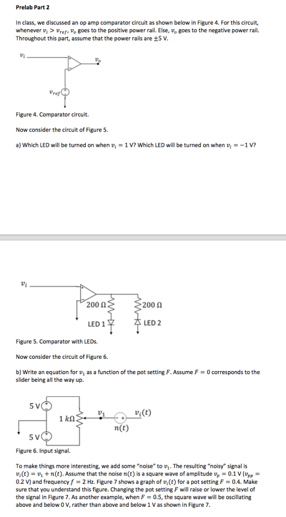

a)Which LED will be turned on when vi = 1V? Which LED will be turned on when vi=-1V?
b) Write an equation for v1 as a function of the pot setting ?. Assume ? = 0 corresponds to the slider being all the way up.
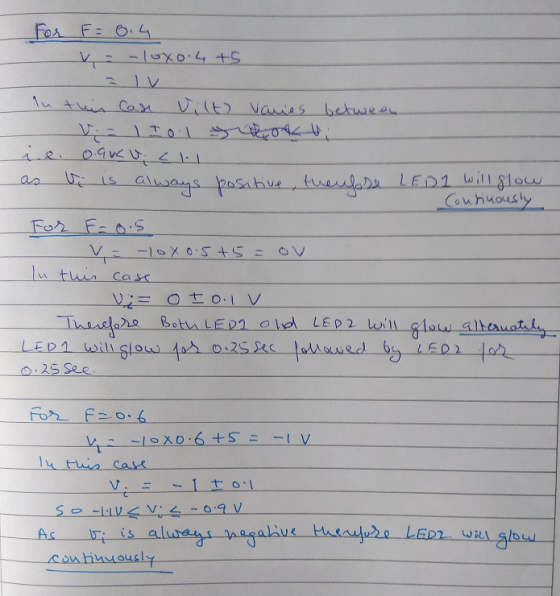
c) What do you expect the LEDs to do for a pot setting of ? = 0.4? How about ? = 0.5? How about ? = 0.6?
d) What is the threshold ? for the Schmitt trigger as shown?
Homework Answers
Answer a)
When Vi is 1V, LED1 will glow.
Explanation: Note that Vi is connected to non-inverting input of the op-amp. And inverting input is grounded (i.e. 0V). Therefore the net input to op-amp (V+ - V-) is positive. Therefore Op-amp out will saturate to nearly +5V. Also notice that anode of LED 1 is towards the op-amp output. Therefore LED 1 will get forward-biased in this case and hence this LED will glow.
Similarly when Vi is -1V, the op-amp output will be nearly -5V. Hence LED2 will get forward-biased and hence it will glow
Answer b)
The required equation is
V1 = -10*F + 5
Where F varies from 0 to 1. Zero mean slider is all the way up and 1 means that the slide is all the way down.
Answer c)
Please see the image below for the analysis of the three values of F.
Answer d) The threshold voltage for the configuration of Schmitt trigger is given by
Vt = ± (R1/R2)*Vs
Here R1 = 20K and R2 = 300K and Vs = 5V
Hence
Vt = ± (20/300)*5 = ±0.33V
Hope this helps
Add Answer to:
a)Which LED will be turned on when vi = 1V? Which LED will be
turned on...
3. Let Vi is AC input signal which has following properties: Voffset: 1 Volt Vpp: 0.5 Volt Wavefo...
 3. Let Vi is AC input signal which has following properties: Voffset: 1 Volt Vpp: 0.5 Volt Waveform: Sinus Frequency: 1 KHz a) Why we chose 1 Volt for offset voltage? b) If the waveform is Square, what would happens in terms of circuit characteristics? How do you make AC Analysis of the circuit to calculate expected output signal? Please explain as step by step. R2-820 0 c) (NPN) R1-100 Figure 1. A transistor circuit
3. Let Vi is AC...
3. Let Vi is AC input signal which has following properties: Voffset: 1 Volt Vpp: 0.5 Volt Waveform: Sinus Frequency: 1 KHz a) Why we chose 1 Volt for offset voltage? b) If the waveform is Square, what would happens in terms of circuit characteristics? How do you make AC Analysis of the circuit to calculate expected output signal? Please explain as step by step. R2-820 0 c) (NPN) R1-100 Figure 1. A transistor circuit
3. Let Vi is AC...
can you show where to measure, the quantity listed in the pic? like what two points...
 can you show where to measure, the quantity listed in the
pic?
like what two points to get the answer
for
all of them, please.
In this step, you will add a second transistor, causing the switching action to improve dramatically. The circuit is shown in Figure 10-2. Notice that the 1.0 k resistor is now the collector resistor for Q. The circuit works as follows. When Vw is very low, Q, is off since it does not have sufficient...
can you show where to measure, the quantity listed in the
pic?
like what two points to get the answer
for
all of them, please.
In this step, you will add a second transistor, causing the switching action to improve dramatically. The circuit is shown in Figure 10-2. Notice that the 1.0 k resistor is now the collector resistor for Q. The circuit works as follows. When Vw is very low, Q, is off since it does not have sufficient...
Question 8 (6 marks) You have been given a 555 Timer, an LED with Von-2V, a 9V battery that can comfortably supply 5mA...
 Question 8 (6 marks) You have been given a 555 Timer, an LED with Von-2V, a 9V battery that can comfortably supply 5mA of current without loss of voltage, a 1uF capacitor and access to any resistor values you want. Design a circuit that causes the LED to flash periodically once per second with a duty cycle of 75% Ensure that it does not draw more than 5mA of current from the battery (i.e 3mA of charging current and 2mA...
Questions 4-20. Questions 4-20. QUESTION 4 the output becomes The longer a signal is applied to...
 Questions 4-20.
QUESTION 4 the output becomes The longer a signal is applied to the input of an integrator op amp, the a smaller b. larger QUESTION 5 the output becomes. The faster the voltage applied to the input of a differentiator changes, the a smaller . b. larger QUESTION 6 voltage than for a negative-going signal. A Schmitt trigger switching threshold for a positive-going input signal is at a a lesser . b.greater QUESTION 7 If a...
Questions 4-20.
Questions 4-20.
QUESTION 4 the output becomes The longer a signal is applied to the input of an integrator op amp, the a smaller b. larger QUESTION 5 the output becomes. The faster the voltage applied to the input of a differentiator changes, the a smaller . b. larger QUESTION 6 voltage than for a negative-going signal. A Schmitt trigger switching threshold for a positive-going input signal is at a a lesser . b.greater QUESTION 7 If a...
ans, RA = 721.5 kohms, RB = 360.8 kohms, R3 = 3.5kohms as an example solution. Question 7 (6 marks) You have been given...
 ans,
RA = 721.5 kohms, RB = 360.8 kohms, R3 = 3.5kohms as an example
solution.
Question 7 (6 marks) You have been given a 555 Timer, an LED with Von 2V, a 9V battery that can comfortably supply 5mA of current without loss of voltage, a 1 μF capacitor and access to any resistor values you want. You are to design a circuit that causes the LED to flash periodically once per second with a duty cycle of 75%....
ans,
RA = 721.5 kohms, RB = 360.8 kohms, R3 = 3.5kohms as an example
solution.
Question 7 (6 marks) You have been given a 555 Timer, an LED with Von 2V, a 9V battery that can comfortably supply 5mA of current without loss of voltage, a 1 μF capacitor and access to any resistor values you want. You are to design a circuit that causes the LED to flash periodically once per second with a duty cycle of 75%....
9 Homework 10 P 9.24 9 of 9 Sketch the load line. Plot the points for t that are separated by the step Av 0.5 V Review Consider the circuit shown in (Figure 1). The diode is the LED having the charact...
 9
Homework 10 P 9.24 9 of 9 Sketch the load line. Plot the points for t that are separated by the step Av 0.5 V Review Consider the circuit shown in (Figure 1). The diode is the LED having the characteristic shown in (Figure 2). Use graphical load ine techniques to solve for f and for the cirouit of (Figure 1 No elements selected i (mA) Figure 1 of2 > 2.5 2 mA 0.5 e (V) 0.0 00 05...
9
Homework 10 P 9.24 9 of 9 Sketch the load line. Plot the points for t that are separated by the step Av 0.5 V Review Consider the circuit shown in (Figure 1). The diode is the LED having the characteristic shown in (Figure 2). Use graphical load ine techniques to solve for f and for the cirouit of (Figure 1 No elements selected i (mA) Figure 1 of2 > 2.5 2 mA 0.5 e (V) 0.0 00 05...
Can anyone help with 3-7? or help me get started? im not sure how to set them up. please and than...
 can anyone help with 3-7? or help me get started? im not sure
how to set them up. please and thank you
I. The Monostable timer (also called the one-shot, abbreviated OS) has 2. Explain the difference between a retriggerable OS and a non A stable state() os gaun until it times ut. 3. Calculate the duration of the pulse generated by a 535 timer circuit configured to operate as an OS. The external resistance used for the generating the...
can anyone help with 3-7? or help me get started? im not sure
how to set them up. please and thank you
I. The Monostable timer (also called the one-shot, abbreviated OS) has 2. Explain the difference between a retriggerable OS and a non A stable state() os gaun until it times ut. 3. Calculate the duration of the pulse generated by a 535 timer circuit configured to operate as an OS. The external resistance used for the generating the...
Could you please show me how I can drw those circuits. please using (NI Multisim 14)...
 Could you please show me how I can drw those circuits.
please using (NI Multisim 14)
Optocoupler Objectives Use an ohmmeter to determine the condition of the optoisolator. Observe the operation of an optocoupler. Determine the maximum frequency response of the optocoupler. Required Materials (1) Dual DC power supply (1) Function generator (1) Oscilloscope (2) Multimeters (1) Optocoupler (ECG3040) (1) 3.9ΚΩ resistor (1) 220 resistor Introduction An optoisolator is a hybrid integrated circuit that contains an LED on one side...
Could you please show me how I can drw those circuits.
please using (NI Multisim 14)
Optocoupler Objectives Use an ohmmeter to determine the condition of the optoisolator. Observe the operation of an optocoupler. Determine the maximum frequency response of the optocoupler. Required Materials (1) Dual DC power supply (1) Function generator (1) Oscilloscope (2) Multimeters (1) Optocoupler (ECG3040) (1) 3.9ΚΩ resistor (1) 220 resistor Introduction An optoisolator is a hybrid integrated circuit that contains an LED on one side...
Need help with schematics for blocks 3, 4 and 5!!!!!! Include all schematics and wiring along with the component values...
 Need help with schematics for blocks 3, 4 and
5!!!!!!
Include all schematics and wiring along with the component
values and how you acquired them. Explain how each block functions
and label any figures.
Need schematics for blocks 3, 4 and 5!!!!!!
Goal For your final project you will be asked to design and assemble a system in which you will input a stereo audio signal, mix the channels into a single mono signal, amplify the signal, filter it to...
Need help with schematics for blocks 3, 4 and
5!!!!!!
Include all schematics and wiring along with the component
values and how you acquired them. Explain how each block functions
and label any figures.
Need schematics for blocks 3, 4 and 5!!!!!!
Goal For your final project you will be asked to design and assemble a system in which you will input a stereo audio signal, mix the channels into a single mono signal, amplify the signal, filter it to...
Question 2: a) Find the value of Vgs? b) If the threshold voltage of the NMOS 0.7V, identify the region o...
 Question 2: a) Find the value of Vgs? b) If the threshold voltage of the NMOS 0.7V, identify the region of operation for the MOSFET (i.e. Triode Saturation or Cutoff) v,= 10V SATE e) Write the formula to calculate Current (ID) for the circuit in Figure 1 Fig. 1 Question 3: a) Find the value of Vgs* b) If the threshold voltage of the NMOS 0.7V, identify the region of operation for the MOSFET (i.e. Triode, Saturation or Cutoff) c)...
 3. Let Vi is AC input signal which has following properties: Voffset: 1 Volt Vpp: 0.5 Volt Waveform: Sinus Frequency: 1 KHz a) Why we chose 1 Volt for offset voltage? b) If the waveform is Square, what would happens in terms of circuit characteristics? How do you make AC Analysis of the circuit to calculate expected output signal? Please explain as step by step. R2-820 0 c) (NPN) R1-100 Figure 1. A transistor circuit
3. Let Vi is AC...
3. Let Vi is AC input signal which has following properties: Voffset: 1 Volt Vpp: 0.5 Volt Waveform: Sinus Frequency: 1 KHz a) Why we chose 1 Volt for offset voltage? b) If the waveform is Square, what would happens in terms of circuit characteristics? How do you make AC Analysis of the circuit to calculate expected output signal? Please explain as step by step. R2-820 0 c) (NPN) R1-100 Figure 1. A transistor circuit
3. Let Vi is AC...
 can you show where to measure, the quantity listed in the
pic?
like what two points to get the answer
for
all of them, please.
In this step, you will add a second transistor, causing the switching action to improve dramatically. The circuit is shown in Figure 10-2. Notice that the 1.0 k resistor is now the collector resistor for Q. The circuit works as follows. When Vw is very low, Q, is off since it does not have sufficient...
can you show where to measure, the quantity listed in the
pic?
like what two points to get the answer
for
all of them, please.
In this step, you will add a second transistor, causing the switching action to improve dramatically. The circuit is shown in Figure 10-2. Notice that the 1.0 k resistor is now the collector resistor for Q. The circuit works as follows. When Vw is very low, Q, is off since it does not have sufficient...
 Question 8 (6 marks) You have been given a 555 Timer, an LED with Von-2V, a 9V battery that can comfortably supply 5mA of current without loss of voltage, a 1uF capacitor and access to any resistor values you want. Design a circuit that causes the LED to flash periodically once per second with a duty cycle of 75% Ensure that it does not draw more than 5mA of current from the battery (i.e 3mA of charging current and 2mA...
 Questions 4-20.
QUESTION 4 the output becomes The longer a signal is applied to the input of an integrator op amp, the a smaller b. larger QUESTION 5 the output becomes. The faster the voltage applied to the input of a differentiator changes, the a smaller . b. larger QUESTION 6 voltage than for a negative-going signal. A Schmitt trigger switching threshold for a positive-going input signal is at a a lesser . b.greater QUESTION 7 If a...
Questions 4-20.
Questions 4-20.
QUESTION 4 the output becomes The longer a signal is applied to the input of an integrator op amp, the a smaller b. larger QUESTION 5 the output becomes. The faster the voltage applied to the input of a differentiator changes, the a smaller . b. larger QUESTION 6 voltage than for a negative-going signal. A Schmitt trigger switching threshold for a positive-going input signal is at a a lesser . b.greater QUESTION 7 If a...
 ans,
RA = 721.5 kohms, RB = 360.8 kohms, R3 = 3.5kohms as an example
solution.
Question 7 (6 marks) You have been given a 555 Timer, an LED with Von 2V, a 9V battery that can comfortably supply 5mA of current without loss of voltage, a 1 μF capacitor and access to any resistor values you want. You are to design a circuit that causes the LED to flash periodically once per second with a duty cycle of 75%....
ans,
RA = 721.5 kohms, RB = 360.8 kohms, R3 = 3.5kohms as an example
solution.
Question 7 (6 marks) You have been given a 555 Timer, an LED with Von 2V, a 9V battery that can comfortably supply 5mA of current without loss of voltage, a 1 μF capacitor and access to any resistor values you want. You are to design a circuit that causes the LED to flash periodically once per second with a duty cycle of 75%....
 9
Homework 10 P 9.24 9 of 9 Sketch the load line. Plot the points for t that are separated by the step Av 0.5 V Review Consider the circuit shown in (Figure 1). The diode is the LED having the characteristic shown in (Figure 2). Use graphical load ine techniques to solve for f and for the cirouit of (Figure 1 No elements selected i (mA) Figure 1 of2 > 2.5 2 mA 0.5 e (V) 0.0 00 05...
9
Homework 10 P 9.24 9 of 9 Sketch the load line. Plot the points for t that are separated by the step Av 0.5 V Review Consider the circuit shown in (Figure 1). The diode is the LED having the characteristic shown in (Figure 2). Use graphical load ine techniques to solve for f and for the cirouit of (Figure 1 No elements selected i (mA) Figure 1 of2 > 2.5 2 mA 0.5 e (V) 0.0 00 05...
 can anyone help with 3-7? or help me get started? im not sure
how to set them up. please and thank you
I. The Monostable timer (also called the one-shot, abbreviated OS) has 2. Explain the difference between a retriggerable OS and a non A stable state() os gaun until it times ut. 3. Calculate the duration of the pulse generated by a 535 timer circuit configured to operate as an OS. The external resistance used for the generating the...
can anyone help with 3-7? or help me get started? im not sure
how to set them up. please and thank you
I. The Monostable timer (also called the one-shot, abbreviated OS) has 2. Explain the difference between a retriggerable OS and a non A stable state() os gaun until it times ut. 3. Calculate the duration of the pulse generated by a 535 timer circuit configured to operate as an OS. The external resistance used for the generating the...
 Could you please show me how I can drw those circuits.
please using (NI Multisim 14)
Optocoupler Objectives Use an ohmmeter to determine the condition of the optoisolator. Observe the operation of an optocoupler. Determine the maximum frequency response of the optocoupler. Required Materials (1) Dual DC power supply (1) Function generator (1) Oscilloscope (2) Multimeters (1) Optocoupler (ECG3040) (1) 3.9ΚΩ resistor (1) 220 resistor Introduction An optoisolator is a hybrid integrated circuit that contains an LED on one side...
Could you please show me how I can drw those circuits.
please using (NI Multisim 14)
Optocoupler Objectives Use an ohmmeter to determine the condition of the optoisolator. Observe the operation of an optocoupler. Determine the maximum frequency response of the optocoupler. Required Materials (1) Dual DC power supply (1) Function generator (1) Oscilloscope (2) Multimeters (1) Optocoupler (ECG3040) (1) 3.9ΚΩ resistor (1) 220 resistor Introduction An optoisolator is a hybrid integrated circuit that contains an LED on one side...
 Need help with schematics for blocks 3, 4 and
5!!!!!!
Include all schematics and wiring along with the component
values and how you acquired them. Explain how each block functions
and label any figures.
Need schematics for blocks 3, 4 and 5!!!!!!
Goal For your final project you will be asked to design and assemble a system in which you will input a stereo audio signal, mix the channels into a single mono signal, amplify the signal, filter it to...
Need help with schematics for blocks 3, 4 and
5!!!!!!
Include all schematics and wiring along with the component
values and how you acquired them. Explain how each block functions
and label any figures.
Need schematics for blocks 3, 4 and 5!!!!!!
Goal For your final project you will be asked to design and assemble a system in which you will input a stereo audio signal, mix the channels into a single mono signal, amplify the signal, filter it to...
 Question 2: a) Find the value of Vgs? b) If the threshold voltage of the NMOS 0.7V, identify the region of operation for the MOSFET (i.e. Triode Saturation or Cutoff) v,= 10V SATE e) Write the formula to calculate Current (ID) for the circuit in Figure 1 Fig. 1 Question 3: a) Find the value of Vgs* b) If the threshold voltage of the NMOS 0.7V, identify the region of operation for the MOSFET (i.e. Triode, Saturation or Cutoff) c)...
Most questions answered within 3 hours.
-
Where is the error in this code sequence?
String s1 = "Hello";
String s2 = "ello";...
asked 10 months ago -
Financial data for Joel de Paris, Inc., for last year
follow:
Joel de Paris, Inc.
Balance...
asked 10 months ago -
Consider this reaction:
Al2(SO4)3 (aq)+ BaCl3
(aq) Al2Cl6 (aq)- +
3BaSO4(s) . What is the...
asked 10 months ago -
Suppose that Savneet is considering increasing her
recent random sample from 20 car rentals to 40...
asked 10 months ago -
Trucks arrive at an unloading terminal at an average rate of 120
per hour.
Trucks arrive...
asked 10 months ago -
Why are methanol and ethanol completely soluble in water while
octanol is not very little soluble....
asked 10 months ago -
A facilities manager at a university reads in a research report
that the mean amount of...
asked 10 months ago -
When the CuSO4 is rehydrated by adding water to the anhydrous
compound, is this an endothermic...
asked 10 months ago -
A ray of sunlight is passing from diamond into crown glass; the
angle of incidence is...
asked 10 months ago -
A block of mass 0.249 kg is placed on top of a light, vertical
spring of...
asked 10 months ago -
how do the kidneys compensate in the presences of acidosis
a) trigger hyperventilate
b) reserve acid...
asked 10 months ago -
Question 501 pts
The rental rate of capital to the firm increases. Which of the
following...
asked 10 months ago