Summarize the various conditions and minimum clearances required for the accurate measurement of peak voltage using...
Summarize the various conditions and minimum clearances required for the accurate measurement of peak voltage using sphere gaps.
Homework Answers
 The breakdown voltages of
uniform and slightly non-uniform electric fields, as
The breakdown voltages of
uniform and slightly non-uniform electric fields, as
e.g., those between sphere electrodes in atmospheric air, show high
stability and low dispersion. Schumann (1923) proposed an empirical
criterion to estimate the criticalfield strength at which
self-sustaining electron avalanches are ignited. modified, this
criterion can also be used to calculate the breakdown voltage Vb of
uniform fields versus the gap spacing S. For a uniform electric
field in air at standard conditions the breakdown voltage can be
approximated by the empirical equation
Vb=kV ¼ 24:4 S þ S
13:1 cm 0:5 " #: ð2:33Þ
This equation is applicable for sphere gaps if the spacing is less
than one-third
of the sphere diameter .
Based on such experimental and theoretical results,
sphere-to-sphere gaps are
used for peak voltage measurement since the early decades of the
twentieth century and led to the first standard of HV testing, the
present IEC 60052:2002.
Meanwhile it is fully understood that this applicability is based
on the so-called
streamer breakdown mechanism, e.g., Meek (1940), Pedersen (1967),
and break- down voltage-gap distance characteristics of sphere gaps
can also be calculated with sufficient accuracy (Petcharales
1986).
For a long time measuring sphere gaps with gap diameters up to 3 m
formed
the impression of HV laboratories. But the voltage measurement by
sphere gaps is connected with the breakdown of the test voltage
therefore their application is not. simple Furthermore they need a
lot of clearances (see below), well maintained clean surfaces of
the spheres and atmospheric corrections for measurement according
to the standard.
Today they are not used for daily HV measurement and do not play
the same important role in HV laboratories as in the past. Their
main application is for performance checks of AMSs or linearity
checks
For acceptance tests on HV apparatus the inspector may require a
check of the applied AMS by a sphere gap to show that it is not
manipulated. For these applications mobile measuring gaps with
sphere diameters D B 50 cm are sufficient.
The IEC Standard on voltage measurement by means of sphere gaps has
been
the oldest IEC standard related to HV testing. Its latest edition
IEC 60052
Ed.3:2002 describes the measurement of AC, DC, LI and SI test
voltage with
horizontal and vertical sphere-to-sphere gaps with sphere diameters
D = (2 …200 cm) and one of the spheres earthed. The spacing S for
voltage measurement is required S B 0.5 D, for rough estimations it
can be extended up to S = 0.75 D. The surfaces shall be smooth with
maximum roughness below 10 lm and free of irregularities in the
region of the sparking point. The curvature has to be as uniform as
possible, characterized by the difference of the diameter of no
morethan 2 %. Minor damages on that part of the hemispherical
surface, which is not involved in the breakdown process, do not
deteriorate the performance of the measuring gap. To avoid erosion
of the surface of the sphere after AC and DC, breakdowns
pre-resistors may be applied of 0.1–1 M9X.
Surrounding objects may influence the results of sphere gap
measurements.
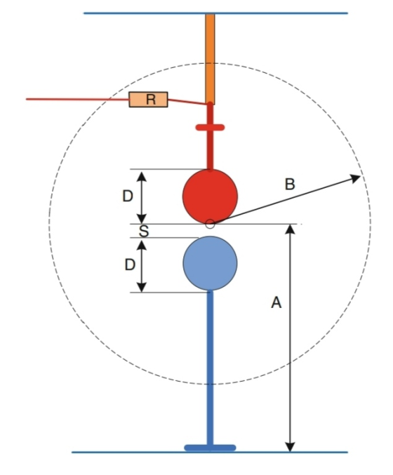
Consequently the dimensions and clearances for standard air gaps
are prescribed in IEC 60052 and shown in Figs. 2.19 and 2.20. The
required range of the height A above ground depends on the sphere
diameter, and is for small spheres A = (7 … 9) D and for large
spheres A = (3 … 4)- D. The clearance to earthed external
structures depends on the gap distance S, and shall be between B =
14 S for small and B = 6 S for large spheres.
The dispersion of the breakdown voltage of a measuring gap depends
strongly
from the availability of a free starting electron, especially for
gaps with
D B 12.5 cm and/or measurement of peak voltages Up B 50 kV.
Starting elec-
trons can be generated by photo ionization (Kuffel 1959; Kachler
1975). The
necessary high energy radiation may come from the far ultra-violet
(UVC) content of nearby corona discharges at AC voltage, or from
the breakdown spark of the openswitching gaps of the used impulse
generator, or a special mercury-vapour UVC lamp with a quartz
tube.
Note In the past, even a radioactive source inside the measuring
sphere has been applied.
For safety reasons this is forbidden now.
Table 2.7 gives the relationship of the measured breakdown voltage
Ub
depending on the distance S between electrodes for some selected
sphere diameters D B 1 m which are mainly used for the mentioned
checks, for other sphere diameters see IEC 60052:2002. A voltage
measurement with a sphere gap means to establish a relation between
an instrument at the power supply input of the HVG (e.g., a primary
voltage measurement at the input of a test transformer) and the
known breakdown voltage of the standard measuring gap in the HV
circuit depending on its gap distance D. This is similar to the
calibration by comparison.
For AC voltage measurement a progressive stress test delivers
10
successive breakdown voltage readings by the instrument. Their mean
value and the relative standard deviation are determined. The
voltage shall be raised sufficiently slowly to allow accurate
readings. The mean value characterizes the breakdown voltage
according to the gap parameters (D, S).
When the standard deviation is B1 %, one can assume that the
measuring gap was correctly maintained and the relative expanded
uncertainty of measurement is B3%.
Note With n = 10 measurements and a standard deviation of 1 % one
gets a standard uncertainty of u = 0.32 % (Eq. 2.14). This means
there are about 1.2 % for the othercontributions to the standard
uncertainty when the expanded uncertainty (k = 2) shall be
B3 % (Eq. 2.29).
For LI/SI voltage measurement, the pre-selected breakdown voltages
(D, S in
Table 2.7) are compared e.g., with charging voltage of the impulse
voltage gen-
erator. The 50 % breakdown voltages U50 are determined in a
multi-level test of
m = 5 voltage levels with n = 10 impulse voltages each (see Sect.
2.4), and the
corresponding reading is taken as the pre-selected reading. When
the evaluated standard deviation is within 1 % for LI and 1.5 % for
SI voltages it is assumed that the measuring gap works
correctly.
For DC voltage measurement, sphere gaps are not recommended
because
external influences as dust or small fibres are charged in a DC
field and cause a
high dispersion. Therefore, a rod–rod measuring gap shall be
applied if the
humidity is not higher than 13 g/m3 (Feser and Hughes 1988; IEC
60052:2002).
The rod electrodes of steel or brass should have a square cross
section of
10–25 mm for each side and sharp edges. When the gap distance S is
between 25 and 250 cm the breakdown is caused by the development of
a streamer discharge of a required average voltage gradient e =
5.34 kV/cm. Then the breakdown voltage can be calculated by
Vb=kV ¼ 2 þ 5:34 -
S=cm: ð2:34Þ
The length of the rods in a vertical arrangement shall be 200 cm,
in a horizontal
gap 100 cm. The rod–rod arrangement should be free of PD at the
connection of the rods to the HV lead, respectively to earth. This
is realized by toroid electrodes for field control. For a
horizontal gap the height above ground should be C400 cm.
The test procedure is as that for AC voltages described above.
Add Answer to:
Summarize the various conditions and minimum clearances required
for the accurate measurement of peak voltage using...
Please help with completing this table? Using the O'scope as the standard measurement device, adjust the...
 Please help with completing this table?
Using the O'scope as the standard measurement device, adjust the function generator for the indicated frequencies and voltage amplitudes, using peak to peak as a reference voltage. If the indicated voltage amplitude is not in peak to peak change it to peak to peak and adjust the function generator appropriately. Fill in each column with the required information: v/div, # of divisions, time/div, the number of divisions for one complete cycle, and period. t/DIV...
Please help with completing this table?
Using the O'scope as the standard measurement device, adjust the function generator for the indicated frequencies and voltage amplitudes, using peak to peak as a reference voltage. If the indicated voltage amplitude is not in peak to peak change it to peak to peak and adjust the function generator appropriately. Fill in each column with the required information: v/div, # of divisions, time/div, the number of divisions for one complete cycle, and period. t/DIV...
An article in the IEEE Transactions on Instrumentation and Measurement ("Direct, Fast, and Accurate Measurement of VT and K of MOS Transistor Using VT-Sift Circuit," 1991, Vol. 40, pp. 951- 9...
 An article in the IEEE Transactions on Instrumentation and Measurement ("Direct, Fast, and Accurate Measurement of VT and K of MOS Transistor Using VT-Sift Circuit," 1991, Vol. 40, pp. 951- 955) described the use of a simple linear regression model to express drain current y (in milliamperes) as a function of ground-to-source voltage x (in volts). The data are as follows: y 0.734 0.886 1.04 1.19 1.351.50 1.66 1.811.972.12 Round your answers to 3 decimal places (a) Fit a simple...
11.57 on Instrumentation and Measurement (Direct, Fast, and Accurate Measurement of VT arnd K of MOS...
 11.57 on Instrumentation and Measurement (Direct, Fast, and Accurate Measurement of VT arnd K of MOS Transistor Using r Sift Circuit, 1991, Vol. 40, pp. 951-955) described the use of a simple linear rearession model to express drairn current y in milliamperes) as a function af ground-to-source voltage x in volts). The data are as fallows: 0.734 0.885 1.04 1.191.351.50 1.66 1.81 1.97 2.12 1.1 1. 1.3 | 1.4 | 1.5 | 1.6 1.7 1.8 1.9 2.0 Round your answers...
1. In solving measurement problems involving the use of annuities, which of these four required conditions...
 1. In solving measurement problems involving the use of annuities, which of these four required conditions are not accurate? a. Periodic cash flows are equal in amount. b. Time periods between the cash flows are the same length. c. Interest rate is constant for each time period. d. Interest is compounded at the beginning of each time period. 2. An annuity in which the cash flows occur on the first day of each period is called an a. ordinary annuity....
Using the Privacy of Individual Health Information lesson, summarize in two paragraphs minimum (in your own...
Using the Privacy of Individual Health Information lesson, summarize in two paragraphs minimum (in your own words using references as support only) two principles that describe an individual’s rights with respect to their PHI. Once you have chosen the two principles, you are to explain what they mean and their importance not only to the patient,
Problem 2.32 Hall effect with ions in ionic crystals By using various sensitive measurement techniques, it...
Problem 2.32 Hall effect with ions in ionic crystals By using various sensitive measurement techniques, it is possible to carry out Hall effect measurements on certain ionic crystals. Stuhrmann, Kreiterling and Funke in 2002 (Solid State Ionics, 154, 109) were able to measure the Hall voltage on superionic RbAg4I5 crystals in a magnetic field. The results at 100 °C indicate that the Hall coefficient is approximately 5.7 × 10⁻⁴ cm3 C-1. The conductivity of the sample at the same temperature...
a) Using the constant voltage drop (CVD) model, what is the minimum input voltage that can...
 a) Using the constant voltage
drop (CVD) model, what is the minimum input
voltage that can reach the MOS circuitry before a diode
turns on, shunting the current to ground? (At this point you
can assume R1 = R2 = 0Ω)
b) Using the constant voltage drop (CVD) model, what is the
maximum input voltage that can reach the MOS
circuitry before a diode turns on, shunting the current to the
supply (Vdd)? (At this point you can assume R1...
a) Using the constant voltage
drop (CVD) model, what is the minimum input
voltage that can reach the MOS circuitry before a diode
turns on, shunting the current to ground? (At this point you
can assume R1 = R2 = 0Ω)
b) Using the constant voltage drop (CVD) model, what is the
maximum input voltage that can reach the MOS
circuitry before a diode turns on, shunting the current to the
supply (Vdd)? (At this point you can assume R1...
please show solution to 4.7 Calculate the peak value of the voltage across the inductor in...
 please show solution to 4.7
Calculate the peak value of the voltage across the inductor in figure 4.7(a), assuming Vo= 10 V, a 2t x 103 s, R= 1 2, L 25 mH, and C 1 uF. 4.6 Calculate the phase of the voltage across the inductor relative to the source in figure 4.7(a) for the values given in problem 4.6 4.7 90 Sinusoldal Circuits circuit-reducti to linear sinusoidal theorems for dc circuits can be applied cuits if the impedances...
please show solution to 4.7
Calculate the peak value of the voltage across the inductor in figure 4.7(a), assuming Vo= 10 V, a 2t x 103 s, R= 1 2, L 25 mH, and C 1 uF. 4.6 Calculate the phase of the voltage across the inductor relative to the source in figure 4.7(a) for the values given in problem 4.6 4.7 90 Sinusoldal Circuits circuit-reducti to linear sinusoidal theorems for dc circuits can be applied cuits if the impedances...
KS31603 SULIT/CONFIDENTIAL QUESTION 4 (20 marks) (a) A message signal has a peak voltage of 1V...
 KS31603 SULIT/CONFIDENTIAL QUESTION 4 (20 marks) (a) A message signal has a peak voltage of 1V and its average power is 125 mW. Design a PCM system (find minimum value of R of the R bit A/D) with uniform quantization to achieve at least a signal to quantization noise ratio of 36 dB. What is the signal to quantization noise ratio obtained in your design? [6 marks] (b) If the signal is sampled at 9kHz in 4(a), what is the...
(20 points) Give a detail design of pressure measurement system by using strain gage as a sensor. The output signal is voltage 1) Draw circuit diagram/and sensing element with strain gauge. 2) Dr...
 (20 points) Give a detail design of pressure measurement system by using strain gage as a sensor. The output signal is voltage 1) Draw circuit diagram/and sensing element with strain gauge. 2) Draw a block diagram and name a part on each block. 3) Give the sensitivity of each block 4) Give an equation to show the relationship of input pressure and output 2. voltage
(20 points) Give a detail design of pressure measurement system by using strain gage as...
(20 points) Give a detail design of pressure measurement system by using strain gage as a sensor. The output signal is voltage 1) Draw circuit diagram/and sensing element with strain gauge. 2) Draw a block diagram and name a part on each block. 3) Give the sensitivity of each block 4) Give an equation to show the relationship of input pressure and output 2. voltage
(20 points) Give a detail design of pressure measurement system by using strain gage as...
 Please help with completing this table?
Using the O'scope as the standard measurement device, adjust the function generator for the indicated frequencies and voltage amplitudes, using peak to peak as a reference voltage. If the indicated voltage amplitude is not in peak to peak change it to peak to peak and adjust the function generator appropriately. Fill in each column with the required information: v/div, # of divisions, time/div, the number of divisions for one complete cycle, and period. t/DIV...
Please help with completing this table?
Using the O'scope as the standard measurement device, adjust the function generator for the indicated frequencies and voltage amplitudes, using peak to peak as a reference voltage. If the indicated voltage amplitude is not in peak to peak change it to peak to peak and adjust the function generator appropriately. Fill in each column with the required information: v/div, # of divisions, time/div, the number of divisions for one complete cycle, and period. t/DIV...
 An article in the IEEE Transactions on Instrumentation and Measurement ("Direct, Fast, and Accurate Measurement of VT and K of MOS Transistor Using VT-Sift Circuit," 1991, Vol. 40, pp. 951- 955) described the use of a simple linear regression model to express drain current y (in milliamperes) as a function of ground-to-source voltage x (in volts). The data are as follows: y 0.734 0.886 1.04 1.19 1.351.50 1.66 1.811.972.12 Round your answers to 3 decimal places (a) Fit a simple...
 11.57 on Instrumentation and Measurement (Direct, Fast, and Accurate Measurement of VT arnd K of MOS Transistor Using r Sift Circuit, 1991, Vol. 40, pp. 951-955) described the use of a simple linear rearession model to express drairn current y in milliamperes) as a function af ground-to-source voltage x in volts). The data are as fallows: 0.734 0.885 1.04 1.191.351.50 1.66 1.81 1.97 2.12 1.1 1. 1.3 | 1.4 | 1.5 | 1.6 1.7 1.8 1.9 2.0 Round your answers...
 1. In solving measurement problems involving the use of annuities, which of these four required conditions are not accurate? a. Periodic cash flows are equal in amount. b. Time periods between the cash flows are the same length. c. Interest rate is constant for each time period. d. Interest is compounded at the beginning of each time period. 2. An annuity in which the cash flows occur on the first day of each period is called an a. ordinary annuity....
 a) Using the constant voltage
drop (CVD) model, what is the minimum input
voltage that can reach the MOS circuitry before a diode
turns on, shunting the current to ground? (At this point you
can assume R1 = R2 = 0Ω)
b) Using the constant voltage drop (CVD) model, what is the
maximum input voltage that can reach the MOS
circuitry before a diode turns on, shunting the current to the
supply (Vdd)? (At this point you can assume R1...
a) Using the constant voltage
drop (CVD) model, what is the minimum input
voltage that can reach the MOS circuitry before a diode
turns on, shunting the current to ground? (At this point you
can assume R1 = R2 = 0Ω)
b) Using the constant voltage drop (CVD) model, what is the
maximum input voltage that can reach the MOS
circuitry before a diode turns on, shunting the current to the
supply (Vdd)? (At this point you can assume R1...
 please show solution to 4.7
Calculate the peak value of the voltage across the inductor in figure 4.7(a), assuming Vo= 10 V, a 2t x 103 s, R= 1 2, L 25 mH, and C 1 uF. 4.6 Calculate the phase of the voltage across the inductor relative to the source in figure 4.7(a) for the values given in problem 4.6 4.7 90 Sinusoldal Circuits circuit-reducti to linear sinusoidal theorems for dc circuits can be applied cuits if the impedances...
please show solution to 4.7
Calculate the peak value of the voltage across the inductor in figure 4.7(a), assuming Vo= 10 V, a 2t x 103 s, R= 1 2, L 25 mH, and C 1 uF. 4.6 Calculate the phase of the voltage across the inductor relative to the source in figure 4.7(a) for the values given in problem 4.6 4.7 90 Sinusoldal Circuits circuit-reducti to linear sinusoidal theorems for dc circuits can be applied cuits if the impedances...
 KS31603 SULIT/CONFIDENTIAL QUESTION 4 (20 marks) (a) A message signal has a peak voltage of 1V and its average power is 125 mW. Design a PCM system (find minimum value of R of the R bit A/D) with uniform quantization to achieve at least a signal to quantization noise ratio of 36 dB. What is the signal to quantization noise ratio obtained in your design? [6 marks] (b) If the signal is sampled at 9kHz in 4(a), what is the...
 (20 points) Give a detail design of pressure measurement system by using strain gage as a sensor. The output signal is voltage 1) Draw circuit diagram/and sensing element with strain gauge. 2) Draw a block diagram and name a part on each block. 3) Give the sensitivity of each block 4) Give an equation to show the relationship of input pressure and output 2. voltage
(20 points) Give a detail design of pressure measurement system by using strain gage as...
(20 points) Give a detail design of pressure measurement system by using strain gage as a sensor. The output signal is voltage 1) Draw circuit diagram/and sensing element with strain gauge. 2) Draw a block diagram and name a part on each block. 3) Give the sensitivity of each block 4) Give an equation to show the relationship of input pressure and output 2. voltage
(20 points) Give a detail design of pressure measurement system by using strain gage as...
Most questions answered within 3 hours.
-
Where is the error in this code sequence?
String s1 = "Hello";
String s2 = "ello";...
asked 10 months ago -
Financial data for Joel de Paris, Inc., for last year
follow:
Joel de Paris, Inc.
Balance...
asked 10 months ago -
Consider this reaction:
Al2(SO4)3 (aq)+ BaCl3
(aq) Al2Cl6 (aq)- +
3BaSO4(s) . What is the...
asked 10 months ago -
Suppose that Savneet is considering increasing her
recent random sample from 20 car rentals to 40...
asked 10 months ago -
Trucks arrive at an unloading terminal at an average rate of 120
per hour.
Trucks arrive...
asked 10 months ago -
Why are methanol and ethanol completely soluble in water while
octanol is not very little soluble....
asked 10 months ago -
A facilities manager at a university reads in a research report
that the mean amount of...
asked 10 months ago -
When the CuSO4 is rehydrated by adding water to the anhydrous
compound, is this an endothermic...
asked 10 months ago -
A ray of sunlight is passing from diamond into crown glass; the
angle of incidence is...
asked 10 months ago -
A block of mass 0.249 kg is placed on top of a light, vertical
spring of...
asked 10 months ago -
how do the kidneys compensate in the presences of acidosis
a) trigger hyperventilate
b) reserve acid...
asked 10 months ago -
Question 501 pts
The rental rate of capital to the firm increases. Which of the
following...
asked 10 months ago