
Homework Answers
Add Answer to:
1921 W/m legenda levent of the beam that is subjected to the distributed lead a Plus...
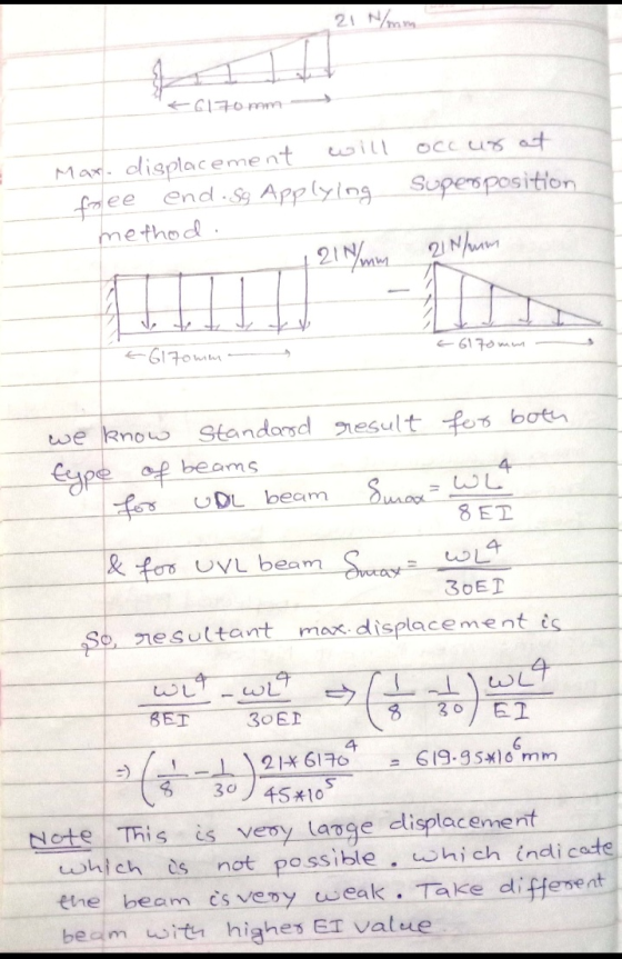
1. (19 pts) The cantilever beam is subjected to a distributed load w (unit N/m) as...
 1. (19 pts) The cantilever beam is subjected to a distributed load w (unit N/m) as shown in the figure. (a) True or false: If the beam is slender, i.e., length, L >> thickness, t, it is reasonable to neglect the shear strain energy, Us, compared with bending energy, UN. ) (b) What are the reaction forces at supports A and B? (c) What is the moment as a function of location along the beam AB? (d) Use energy method...
The simply supported beam of length L is subjected to uniformly distributed load of w and...
 The simply supported beam of length L is subjected to uniformly distributed load of w and a vertical point load P at its middle, as shown in Figure Q3. Both young's modulus and second moment of area of this structure are given as E and I. Please provide your answers in terms of letters w, P,L,1, E. Self-weight of the beam is neglected. P W L/2 L/2 Figure Q3 (a) Determine the reactions, bending moment equation along the beam and...
The beam having a cross-section as shown is subjected to the distributed load w (1) Calculate...
 The beam having a cross-section as shown is subjected to the distributed load w (1) Calculate the moment of inertia, I (2) If the allowable maximum normal stress ơmax-20 MPa, determine the largest distributed load 5. w. (3) If w 1.5 kN/m, determine the maximum bending stress in the beam. Sketch the stress distribution acting over the cross-section. 100 mm 50mm 120 mm 3 m50 mm 3 m
The simply supported beam is subjected to a uniform distributed load, w of 30 kN/m in...
 The simply supported beam is subjected to a uniform distributed load, w of 30 kN/m in the negative y-direction and a point load, P of 15 kN in the negative z-direction. The total length, L of the beam is 6 m. Answer the questions that follow: 'n Eenvoudige opgelegde balk word belas met 'n uniform verspreide belasting van w 30 kN/m in die negatiewe y-rigting en 'n puntlas P = 15 kN in die negatiewe z-rigting. Die totale lengte, L...
Q2 The 10 m long simply supported beam is subjected to a uniformly distributed load w...
 Q2 The 10 m long simply supported beam is subjected to a uniformly distributed load w = 10 kN/m throughout and a point load P =10 kN at the midspan of the beam, as shown in Figure Q2 (a). The cross section of this beam is depicted in Figure Q2 (b), which consists of three equal rectangular steel members. Self-weight of the beam is neglected. 30 mm P= 10 KN W = 10 kN/m 200 mm 5 m 5 m...
Q2 The 10 m long simply supported beam is subjected to a uniformly distributed load w...
 Q2 The 10 m long simply supported beam is subjected to a uniformly distributed load w = 10 kN/m throughout and a point load P =10 kN at the midspan of the beam, as shown in Figure Q2 (a). The cross section of this beam is depicted in Figure Q2 (b), which consists of three equal rectangular steel members. Self-weight of the beam is neglected. 30 mm P = 10 kN W = 10 kN/m 200 mm 5 m 5...
Q2 The 10 m long simply supported beam is subjected to a uniformly distributed load w...
 Q2 The 10 m long simply supported beam is subjected to a uniformly distributed load w = 10 kN/m throughout and a point load P =10 kN at the midspan of the beam, as shown in Figure Q2 (a). The cross section of this beam is depicted in Figure Q2 (b), which consists of three equal rectangular steel members. Self-weight of the beam is neglected. 30 mm P = 10 kN w = 10 kN/m 200 mm 5 m 5...
The overhang beam is subjected to the uniform distributed load having an intensity of w = 46 kN/m (Figure 1)
 The overhang beam is subjected to the uniform distributed load having an intensity of w = 46 kN/m (Figure 1) Part A Determine the maximum shear stress developed in the beam.
The reinforced concrete beam shown in Figure-2 is to be subjected to the following uniformly distributed...
 The reinforced concrete beam shown in Figure-2 is to be subjected to the following uniformly distributed loads over the entire length: DL = 14 kn/m (including self-weight) and LL = 20kN/m, fc = 32 MPa. For architectural reasons the beam width is set at 500 mm. Determine the effective depth required if ku = 0.25 for the section of maximum positive bending moment. Then design the reinforcement required. zin Figure-2
If the beam is subjected to a bending moment of M - 20 kN . m,...
 If the beam is subjected to a bending moment of M - 20 kN . m, determine the maximum bending stress in the beam.
 1. (19 pts) The cantilever beam is subjected to a distributed load w (unit N/m) as shown in the figure. (a) True or false: If the beam is slender, i.e., length, L >> thickness, t, it is reasonable to neglect the shear strain energy, Us, compared with bending energy, UN. ) (b) What are the reaction forces at supports A and B? (c) What is the moment as a function of location along the beam AB? (d) Use energy method...
 The simply supported beam of length L is subjected to uniformly distributed load of w and a vertical point load P at its middle, as shown in Figure Q3. Both young's modulus and second moment of area of this structure are given as E and I. Please provide your answers in terms of letters w, P,L,1, E. Self-weight of the beam is neglected. P W L/2 L/2 Figure Q3 (a) Determine the reactions, bending moment equation along the beam and...
 The beam having a cross-section as shown is subjected to the distributed load w (1) Calculate the moment of inertia, I (2) If the allowable maximum normal stress ơmax-20 MPa, determine the largest distributed load 5. w. (3) If w 1.5 kN/m, determine the maximum bending stress in the beam. Sketch the stress distribution acting over the cross-section. 100 mm 50mm 120 mm 3 m50 mm 3 m
 The simply supported beam is subjected to a uniform distributed load, w of 30 kN/m in the negative y-direction and a point load, P of 15 kN in the negative z-direction. The total length, L of the beam is 6 m. Answer the questions that follow: 'n Eenvoudige opgelegde balk word belas met 'n uniform verspreide belasting van w 30 kN/m in die negatiewe y-rigting en 'n puntlas P = 15 kN in die negatiewe z-rigting. Die totale lengte, L...
 Q2 The 10 m long simply supported beam is subjected to a uniformly distributed load w = 10 kN/m throughout and a point load P =10 kN at the midspan of the beam, as shown in Figure Q2 (a). The cross section of this beam is depicted in Figure Q2 (b), which consists of three equal rectangular steel members. Self-weight of the beam is neglected. 30 mm P= 10 KN W = 10 kN/m 200 mm 5 m 5 m...
 Q2 The 10 m long simply supported beam is subjected to a uniformly distributed load w = 10 kN/m throughout and a point load P =10 kN at the midspan of the beam, as shown in Figure Q2 (a). The cross section of this beam is depicted in Figure Q2 (b), which consists of three equal rectangular steel members. Self-weight of the beam is neglected. 30 mm P = 10 kN W = 10 kN/m 200 mm 5 m 5...
 Q2 The 10 m long simply supported beam is subjected to a uniformly distributed load w = 10 kN/m throughout and a point load P =10 kN at the midspan of the beam, as shown in Figure Q2 (a). The cross section of this beam is depicted in Figure Q2 (b), which consists of three equal rectangular steel members. Self-weight of the beam is neglected. 30 mm P = 10 kN w = 10 kN/m 200 mm 5 m 5...
 The reinforced concrete beam shown in Figure-2 is to be subjected to the following uniformly distributed loads over the entire length: DL = 14 kn/m (including self-weight) and LL = 20kN/m, fc = 32 MPa. For architectural reasons the beam width is set at 500 mm. Determine the effective depth required if ku = 0.25 for the section of maximum positive bending moment. Then design the reinforcement required. zin Figure-2
 If the beam is subjected to a bending moment of M - 20 kN . m, determine the maximum bending stress in the beam.
Most questions answered within 3 hours.
-
Where is the error in this code sequence?
String s1 = "Hello";
String s2 = "ello";...
asked 11 months ago -
Financial data for Joel de Paris, Inc., for last year
follow:
Joel de Paris, Inc.
Balance...
asked 11 months ago -
Consider this reaction:
Al2(SO4)3 (aq)+ BaCl3
(aq) Al2Cl6 (aq)- +
3BaSO4(s) . What is the...
asked 11 months ago -
Suppose that Savneet is considering increasing her
recent random sample from 20 car rentals to 40...
asked 11 months ago -
Trucks arrive at an unloading terminal at an average rate of 120
per hour.
Trucks arrive...
asked 11 months ago -
Why are methanol and ethanol completely soluble in water while
octanol is not very little soluble....
asked 11 months ago -
A facilities manager at a university reads in a research report
that the mean amount of...
asked 11 months ago -
When the CuSO4 is rehydrated by adding water to the anhydrous
compound, is this an endothermic...
asked 11 months ago -
A ray of sunlight is passing from diamond into crown glass; the
angle of incidence is...
asked 11 months ago -
A block of mass 0.249 kg is placed on top of a light, vertical
spring of...
asked 11 months ago -
how do the kidneys compensate in the presences of acidosis
a) trigger hyperventilate
b) reserve acid...
asked 11 months ago -
Question 501 pts
The rental rate of capital to the firm increases. Which of the
following...
asked 11 months ago