
Homework Answers


Add Answer to:
Problem 2: Sketch the output voltage waveform for each of the following circuits showing clearly the...
1. For the 4 circuits shown below, sketch the output waveform for a 1V peak, 1kHz,...
 1. For the 4 circuits shown below, sketch the output waveform for a 1V peak, 1kHz, sinusoidal wave in put signal. Assume the diodes are ideal and they exhibit ON-OFF switch model behaviour. Create an ideal diode model in LT-Spice with the following specification [.model IdealDiode D(Ron=0.1m Roff=100G Vfwd-0.0) ] simulate the circuit and verify the output waveform. Vin Vout Vin Vout 1k 1k (a) (b) 1k Vin 1k Vin Vout Vout ww 1k (c) (d) KH
1. For the...
1. For the 4 circuits shown below, sketch the output waveform for a 1V peak, 1kHz, sinusoidal wave in put signal. Assume the diodes are ideal and they exhibit ON-OFF switch model behaviour. Create an ideal diode model in LT-Spice with the following specification [.model IdealDiode D(Ron=0.1m Roff=100G Vfwd-0.0) ] simulate the circuit and verify the output waveform. Vin Vout Vin Vout 1k 1k (a) (b) 1k Vin 1k Vin Vout Vout ww 1k (c) (d) KH
1. For the...
2. Diode circuits and output waveforms. (a) Sketch the output waveforms expected when a 100Hz, 6V...
 2. Diode circuits and output waveforms. (a) Sketch the output waveforms expected when a 100Hz, 6Vp sine wave is applied to each of the circuits shown. Label important voltage levels and time values. Your plots should be large enough, at least 4 to 6 inches on a side, and semi-quantitative to represent accurately the output waveform. Note: the input signal is ap- plied to the left side of the circuit and the output taken from the two terminals on the...
24) For the three circuits (a), (b) and (c) shown below, the waveform of input voltage...
 24) For the three circuits (a), (b) and (c) shown below, the waveform of input voltage vy is given as shown below. For each circuit, sketch the waveform of output voltage vo for the given input voltage . Label the most positive and most negative output levels. Assume all diodes are ideal (vp- 0) and CR>> T. (10 points) +10 V-- -10 V TI ms (3 points) (b) o- (3 points) 3V (4 points) DH
Question 5: Sketch the output waveform V, and calculate the hysteresis voltage Vy for the following...
 Question 5: Sketch the output waveform V, and calculate the hysteresis voltage Vy for the following circuit a) +15 V 10 sin ot Volto VO -15 V R2 R w 10 kΩ 30 kΩ b) If the 10 k 2 resistor in (a) above is not grounded, but is instead connected to DC voltage source of +7V, sketch V, and calculate the new value of V.
Or the following circuit, sketch the output voltage, given an input voltage waveform as shown on ...
 or the following circuit, sketch the output voltage, given an input voltage waveform as shown on the axes below. Assume a constant voltage drop diode model with Vo- 0.7. +15.0V 4 1mA OVout 3009 3 Vo -4 0 0.2 0.4 0.6 0.8 in
or the following circuit, sketch the output voltage, given an input voltage waveform as shown on the axes below. Assume a constant voltage drop diode model with Vo- 0.7. +15.0V 4 1mA OVout 3009 3 Vo -4...
or the following circuit, sketch the output voltage, given an input voltage waveform as shown on the axes below. Assume a constant voltage drop diode model with Vo- 0.7. +15.0V 4 1mA OVout 3009 3 Vo -4 0 0.2 0.4 0.6 0.8 in
or the following circuit, sketch the output voltage, given an input voltage waveform as shown on the axes below. Assume a constant voltage drop diode model with Vo- 0.7. +15.0V 4 1mA OVout 3009 3 Vo -4...
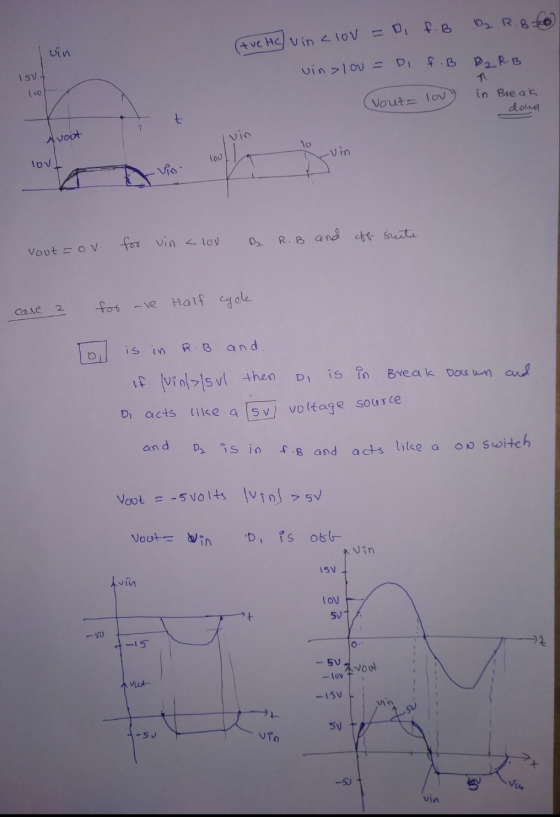
2. Sketch Vout VS Vin and Vout if Vin-10sin(2TT60t) for each of the following circuits. You may a...
 2. Sketch Vout VS Vin and Vout if Vin-10sin(2TT60t) for each of the following circuits. You may assume that the forward diode drops for the diodes equals zero Vout s v out Vin 5 V Vout out 3. Repeat problem 2 but with forward diode drops equal to 0.7 V 4. What are the primary mechanisms for current flow in a. A forward biased diode. b. A reverse biased diode not in breakdown. c. A reverse biased diode in breakdown...
Sketch the output Vout of the following circuits as a function of Vin. Mark and expressx- and y- intercepts in terms of parameters given in the drawing. (Hint: voltage divider) Vin Vref-AW R2 Vout VE...
 Sketch the output Vout of the following circuits as a function of Vin. Mark and expressx- and y- intercepts in terms of parameters given in the drawing. (Hint: voltage divider) Vin Vref-AW R2 Vout VEE
Sketch the output Vout of the following circuits as a function of Vin. Mark and expressx- and y- intercepts in terms of parameters given in the drawing. (Hint: voltage divider) Vin Vref-AW R2 Vout VEE
Sketch the output Vout of the following circuits as a function of Vin. Mark and expressx- and y- intercepts in terms of parameters given in the drawing. (Hint: voltage divider) Vin Vref-AW R2 Vout VEE
Department of Engineering TechnologY 3. For the circuit shown below: (10 pts) ETEE 2320 Circuits &Systems...
 Department of Engineering TechnologY 3. For the circuit shown below: (10 pts) ETEE 2320 Circuits &Systems (E-Tech I) Final, 5/8/19 Ri (a) Calculate the output voltage Van at f, resonant 20 0 200 V RMS Vout Redon Winding R 11.25 ma (b) Calculate Q filter Quality factor and BW bandwidth (c) Draw the V vs f response showing voltage as 100% and 70.7 % of the output values, indicate Bw. 100% Vout 70.7% Vout 4. For each transformer (trf) shown...
Consider the circuits below with ideal diodes, R = 2 ks, C = 1 uF, and...
 Consider the circuits below with ideal diodes, R = 2 ks, C = 1 uF, and Vbi = VB2 = 3 V. (a) Calculate the current through D, and the output voltage for vin1 = 5 V (i.e. constant). (b) Calculate the current through D, and the output voltage for Vin2 = 5 V (i.e. constant). (c) Find the maximum and minimum values of the output voltage vouti(t) when the input voltage Vini(t) is a 10-V peak-to-peak sinusoids with zero...
1) Calculate the closed-loop voltage gain ACL for the given circuit. 2) Calculate the output voltage...
 1) Calculate the closed-loop voltage gain
ACL for the given circuit.
2) Calculate the output voltage Vout in the
circuit. (VPP)
Required information In the circuit below: Ri = 7.5 k2 and RF = 82 k12. SR = 0.5 V/us Avol = 100,000 RE Zout/OL) = 7502 funity = 1 MHz WW R +15 V 741 + ) Vin = 1 VP-P Vout -15 V
1) Calculate the closed-loop voltage gain
ACL for the given circuit.
2) Calculate the output voltage Vout in the
circuit. (VPP)
Required information In the circuit below: Ri = 7.5 k2 and RF = 82 k12. SR = 0.5 V/us Avol = 100,000 RE Zout/OL) = 7502 funity = 1 MHz WW R +15 V 741 + ) Vin = 1 VP-P Vout -15 V
 1. For the 4 circuits shown below, sketch the output waveform for a 1V peak, 1kHz, sinusoidal wave in put signal. Assume the diodes are ideal and they exhibit ON-OFF switch model behaviour. Create an ideal diode model in LT-Spice with the following specification [.model IdealDiode D(Ron=0.1m Roff=100G Vfwd-0.0) ] simulate the circuit and verify the output waveform. Vin Vout Vin Vout 1k 1k (a) (b) 1k Vin 1k Vin Vout Vout ww 1k (c) (d) KH
1. For the...
1. For the 4 circuits shown below, sketch the output waveform for a 1V peak, 1kHz, sinusoidal wave in put signal. Assume the diodes are ideal and they exhibit ON-OFF switch model behaviour. Create an ideal diode model in LT-Spice with the following specification [.model IdealDiode D(Ron=0.1m Roff=100G Vfwd-0.0) ] simulate the circuit and verify the output waveform. Vin Vout Vin Vout 1k 1k (a) (b) 1k Vin 1k Vin Vout Vout ww 1k (c) (d) KH
1. For the...
 2. Diode circuits and output waveforms. (a) Sketch the output waveforms expected when a 100Hz, 6Vp sine wave is applied to each of the circuits shown. Label important voltage levels and time values. Your plots should be large enough, at least 4 to 6 inches on a side, and semi-quantitative to represent accurately the output waveform. Note: the input signal is ap- plied to the left side of the circuit and the output taken from the two terminals on the...
 24) For the three circuits (a), (b) and (c) shown below, the waveform of input voltage vy is given as shown below. For each circuit, sketch the waveform of output voltage vo for the given input voltage . Label the most positive and most negative output levels. Assume all diodes are ideal (vp- 0) and CR>> T. (10 points) +10 V-- -10 V TI ms (3 points) (b) o- (3 points) 3V (4 points) DH
 Question 5: Sketch the output waveform V, and calculate the hysteresis voltage Vy for the following circuit a) +15 V 10 sin ot Volto VO -15 V R2 R w 10 kΩ 30 kΩ b) If the 10 k 2 resistor in (a) above is not grounded, but is instead connected to DC voltage source of +7V, sketch V, and calculate the new value of V.
 or the following circuit, sketch the output voltage, given an input voltage waveform as shown on the axes below. Assume a constant voltage drop diode model with Vo- 0.7. +15.0V 4 1mA OVout 3009 3 Vo -4 0 0.2 0.4 0.6 0.8 in
or the following circuit, sketch the output voltage, given an input voltage waveform as shown on the axes below. Assume a constant voltage drop diode model with Vo- 0.7. +15.0V 4 1mA OVout 3009 3 Vo -4...
or the following circuit, sketch the output voltage, given an input voltage waveform as shown on the axes below. Assume a constant voltage drop diode model with Vo- 0.7. +15.0V 4 1mA OVout 3009 3 Vo -4 0 0.2 0.4 0.6 0.8 in
or the following circuit, sketch the output voltage, given an input voltage waveform as shown on the axes below. Assume a constant voltage drop diode model with Vo- 0.7. +15.0V 4 1mA OVout 3009 3 Vo -4...
 2. Sketch Vout VS Vin and Vout if Vin-10sin(2TT60t) for each of the following circuits. You may assume that the forward diode drops for the diodes equals zero Vout s v out Vin 5 V Vout out 3. Repeat problem 2 but with forward diode drops equal to 0.7 V 4. What are the primary mechanisms for current flow in a. A forward biased diode. b. A reverse biased diode not in breakdown. c. A reverse biased diode in breakdown...
 Sketch the output Vout of the following circuits as a function of Vin. Mark and expressx- and y- intercepts in terms of parameters given in the drawing. (Hint: voltage divider) Vin Vref-AW R2 Vout VEE
Sketch the output Vout of the following circuits as a function of Vin. Mark and expressx- and y- intercepts in terms of parameters given in the drawing. (Hint: voltage divider) Vin Vref-AW R2 Vout VEE
Sketch the output Vout of the following circuits as a function of Vin. Mark and expressx- and y- intercepts in terms of parameters given in the drawing. (Hint: voltage divider) Vin Vref-AW R2 Vout VEE
 Department of Engineering TechnologY 3. For the circuit shown below: (10 pts) ETEE 2320 Circuits &Systems (E-Tech I) Final, 5/8/19 Ri (a) Calculate the output voltage Van at f, resonant 20 0 200 V RMS Vout Redon Winding R 11.25 ma (b) Calculate Q filter Quality factor and BW bandwidth (c) Draw the V vs f response showing voltage as 100% and 70.7 % of the output values, indicate Bw. 100% Vout 70.7% Vout 4. For each transformer (trf) shown...
 Consider the circuits below with ideal diodes, R = 2 ks, C = 1 uF, and Vbi = VB2 = 3 V. (a) Calculate the current through D, and the output voltage for vin1 = 5 V (i.e. constant). (b) Calculate the current through D, and the output voltage for Vin2 = 5 V (i.e. constant). (c) Find the maximum and minimum values of the output voltage vouti(t) when the input voltage Vini(t) is a 10-V peak-to-peak sinusoids with zero...
 1) Calculate the closed-loop voltage gain
ACL for the given circuit.
2) Calculate the output voltage Vout in the
circuit. (VPP)
Required information In the circuit below: Ri = 7.5 k2 and RF = 82 k12. SR = 0.5 V/us Avol = 100,000 RE Zout/OL) = 7502 funity = 1 MHz WW R +15 V 741 + ) Vin = 1 VP-P Vout -15 V
1) Calculate the closed-loop voltage gain
ACL for the given circuit.
2) Calculate the output voltage Vout in the
circuit. (VPP)
Required information In the circuit below: Ri = 7.5 k2 and RF = 82 k12. SR = 0.5 V/us Avol = 100,000 RE Zout/OL) = 7502 funity = 1 MHz WW R +15 V 741 + ) Vin = 1 VP-P Vout -15 V
Most questions answered within 3 hours.
-
Where is the error in this code sequence?
String s1 = "Hello";
String s2 = "ello";...
asked 10 months ago -
Financial data for Joel de Paris, Inc., for last year
follow:
Joel de Paris, Inc.
Balance...
asked 10 months ago -
Consider this reaction:
Al2(SO4)3 (aq)+ BaCl3
(aq) Al2Cl6 (aq)- +
3BaSO4(s) . What is the...
asked 10 months ago -
Suppose that Savneet is considering increasing her
recent random sample from 20 car rentals to 40...
asked 10 months ago -
Trucks arrive at an unloading terminal at an average rate of 120
per hour.
Trucks arrive...
asked 10 months ago -
Why are methanol and ethanol completely soluble in water while
octanol is not very little soluble....
asked 10 months ago -
A facilities manager at a university reads in a research report
that the mean amount of...
asked 10 months ago -
When the CuSO4 is rehydrated by adding water to the anhydrous
compound, is this an endothermic...
asked 10 months ago -
A ray of sunlight is passing from diamond into crown glass; the
angle of incidence is...
asked 10 months ago -
A block of mass 0.249 kg is placed on top of a light, vertical
spring of...
asked 10 months ago -
how do the kidneys compensate in the presences of acidosis
a) trigger hyperventilate
b) reserve acid...
asked 10 months ago -
Question 501 pts
The rental rate of capital to the firm increases. Which of the
following...
asked 10 months ago