Please show all steps and applicable diagrams
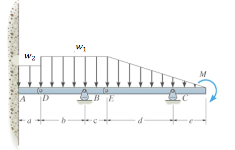
a = 2.0m
b = 4.0m
c = 2.0m
d = 6.0m
e = 3.0m
M = 48kN*m
w1 = 8kN/m
w2 = 6kN/m

Homework Answers
Solution...


Add Answer to:
Please show all steps and applicable diagrams
a = 2.0m
b = 4.0m
c = 2.0m...
u Review Part B - Calculate the moment of inertia Learning Goal: To find the centroid...
 u Review Part B - Calculate the moment of inertia Learning Goal: To find the centroid and moment of inertia of an I-beam's cross section, and to use the flexure formula to find the stress at a point on the cross section due to an internal bending moment. Once the position of the centroid is known, the moment of inertia can be calculated. What is the moment of inertia of the section for bending around the z-axis? Express your answer...
4. (30%) For a beam with a T-section as shown, the cross-sectional dimensions of 12 mm....
 4. (30%) For a beam with a T-section as shown, the cross-sectional dimensions of 12 mm. The centroid is 75 mm, h = 90 mm, t the beam are b 60 mm, h, at C and c 30 mm. At a certain section of the beam, the bending moment is M 5.4 kN m and the vertical shear force is V= 30 kN. (a) Show that the moment of inertia of the cross-section about the z axis (the neutral axis)...
please help 30 k 12" A 4 ft Equation sheet may be accessed here. Calculate the...
 please help
30 k 12" A 4 ft Equation sheet may be accessed here. Calculate the maximum normal bending stress and the maximum transverse shear stress on the beam. Use no more than 3 significant figures in your answer, and do not repeat units in your answer. (1) What is the maximum shear demand on the beam in kips? (2) What is the maximum moment demand on the beam in kip-ft? (3) What is the moment of inertia for the...
please help
30 k 12" A 4 ft Equation sheet may be accessed here. Calculate the maximum normal bending stress and the maximum transverse shear stress on the beam. Use no more than 3 significant figures in your answer, and do not repeat units in your answer. (1) What is the maximum shear demand on the beam in kips? (2) What is the maximum moment demand on the beam in kip-ft? (3) What is the moment of inertia for the...
3) (40 pts) The EXTERNAL 35 kN force P is applied to the end of a 2 m long cantilever beam with t...
 3) (40 pts) The EXTERNAL 35 kN force P is applied to the end of a 2 m long cantilever beam with the given cross section. The force acts through the shear center, forming an angle of 35 with the horizontal axis. The x, y axes pass through the centroid C. The y-axis can be assumed to coincide with the right- hand edge of the vertical section. Determine (a) the normal bending stress at Point A, (b) normal bending stress...
The simply supported beam is subjected to a uniform distributed load, w of 30 kN/m in...
 The simply supported beam is subjected to a uniform distributed load, w of 30 kN/m in the negative y-direction and a point load, P of 15 kN in the negative z-direction. The total length, L of the beam is 6 m. Answer the questions that follow: 'n Eenvoudige opgelegde balk word belas met 'n uniform verspreide belasting van w 30 kN/m in die negatiewe y-rigting en 'n puntlas P = 15 kN in die negatiewe z-rigting. Die totale lengte, L...
a. Determine the reaction forces.
 a. Determine the reaction forces.b. Determine the location of neutral axis with the given geometry.c. Determine the moment of inertia about the neutral axis.d. Draw shear force diagram.e. Draw bending moment diagram.f. Determine the maximum positive and maximum negative shear forces and their locations.g. Determine the maximum positive and maximum negative bending moments and their locations.h. Determine the maximum tensile and compressive bending stresses associated with the maximum positive moment.i. Determine the maximum tensile and compressive bending stresses associated with...
2 1 0 T" A(1/r)dA=b-In(r/r The figure (not drawn to scale) shows a curved I-beam of given section and inner rad...
 2 1 0 T" A(1/r)dA=b-In(r/r The figure (not drawn to scale) shows a curved I-beam of given section and inner radius subjected to a bending moment. Given Sections parameters w 12 mm, h 115 mm, w85mm and he 21 mm, Inner radlus Ro320 mm, and bending moment M 850 MPa Calculate the radius of curvature at the beam's section centroid F, the radius of curvature at the neutral axis R and the stress at point Bop
2 1 0
T"...
2 1 0 T" A(1/r)dA=b-In(r/r The figure (not drawn to scale) shows a curved I-beam of given section and inner radius subjected to a bending moment. Given Sections parameters w 12 mm, h 115 mm, w85mm and he 21 mm, Inner radlus Ro320 mm, and bending moment M 850 MPa Calculate the radius of curvature at the beam's section centroid F, the radius of curvature at the neutral axis R and the stress at point Bop
2 1 0
T"...
1. A beam has a max moment of 45 kN-m. The cross section of the beam is shown in the figure below...
 1. A beam has a max moment of 45 kN-m. The cross section of the beam is shown in the figure below. a. State the distance of the centroid from the 2 axis. b. Calculate the area moment of inertia about the centroid. c. Calculate the maximum stress in the beam 300 mm 20 mm 185 mm 20 mm 35 mm
1. A beam has a max moment of 45 kN-m. The cross section of the beam is shown in...
1. A beam has a max moment of 45 kN-m. The cross section of the beam is shown in the figure below. a. State the distance of the centroid from the 2 axis. b. Calculate the area moment of inertia about the centroid. c. Calculate the maximum stress in the beam 300 mm 20 mm 185 mm 20 mm 35 mm
1. A beam has a max moment of 45 kN-m. The cross section of the beam is shown in...
(Q2) For the shown beam, a uniformly distributed load is applied across the beam length. The...
 (Q2) For the shown beam, a uniformly distributed load is applied across the beam length. The beam cross section is symmetrical. The beam length and cross-sectional dimensions are shown in figure. 40 mm B С 300 mm 10 N/m N A 40 mm 300 mm 40 mm 500 mm 1- Plot the Shear Force Distribution (with values) 2- Plot the Bending Moment Distribution (with values) 3. Determine the maximum Moment value and indicate the most critical section 4- Calculate the...
Cross-section of a beam is shown left Pure bending about a horizontal axis (upward) M-2000N. m St...
 Cross-section of a beam is shown left Pure bending about a horizontal axis (upward) M-2000N. m Steel: E-200GPa Aluminum: E-100GPa Steel 20 mm 40 mm Aluminum Choose Aluminum as the reference material, calculate modulus ratio, ni(for steel) and n2 (for aluminum) Find location of Neutral Axis Y Y starting from the bottom line) a) 30 mm n.A.Y b) (choose c) Calculate (reference) moment of inertia, I d) Determine maximum stress(magnitude) in the steel Determine the bending curvature n, My e)...
 u Review Part B - Calculate the moment of inertia Learning Goal: To find the centroid and moment of inertia of an I-beam's cross section, and to use the flexure formula to find the stress at a point on the cross section due to an internal bending moment. Once the position of the centroid is known, the moment of inertia can be calculated. What is the moment of inertia of the section for bending around the z-axis? Express your answer...
 4. (30%) For a beam with a T-section as shown, the cross-sectional dimensions of 12 mm. The centroid is 75 mm, h = 90 mm, t the beam are b 60 mm, h, at C and c 30 mm. At a certain section of the beam, the bending moment is M 5.4 kN m and the vertical shear force is V= 30 kN. (a) Show that the moment of inertia of the cross-section about the z axis (the neutral axis)...
 please help
30 k 12" A 4 ft Equation sheet may be accessed here. Calculate the maximum normal bending stress and the maximum transverse shear stress on the beam. Use no more than 3 significant figures in your answer, and do not repeat units in your answer. (1) What is the maximum shear demand on the beam in kips? (2) What is the maximum moment demand on the beam in kip-ft? (3) What is the moment of inertia for the...
please help
30 k 12" A 4 ft Equation sheet may be accessed here. Calculate the maximum normal bending stress and the maximum transverse shear stress on the beam. Use no more than 3 significant figures in your answer, and do not repeat units in your answer. (1) What is the maximum shear demand on the beam in kips? (2) What is the maximum moment demand on the beam in kip-ft? (3) What is the moment of inertia for the...
 3) (40 pts) The EXTERNAL 35 kN force P is applied to the end of a 2 m long cantilever beam with the given cross section. The force acts through the shear center, forming an angle of 35 with the horizontal axis. The x, y axes pass through the centroid C. The y-axis can be assumed to coincide with the right- hand edge of the vertical section. Determine (a) the normal bending stress at Point A, (b) normal bending stress...
 The simply supported beam is subjected to a uniform distributed load, w of 30 kN/m in the negative y-direction and a point load, P of 15 kN in the negative z-direction. The total length, L of the beam is 6 m. Answer the questions that follow: 'n Eenvoudige opgelegde balk word belas met 'n uniform verspreide belasting van w 30 kN/m in die negatiewe y-rigting en 'n puntlas P = 15 kN in die negatiewe z-rigting. Die totale lengte, L...
 a. Determine the reaction forces.b. Determine the location of neutral axis with the given geometry.c. Determine the moment of inertia about the neutral axis.d. Draw shear force diagram.e. Draw bending moment diagram.f. Determine the maximum positive and maximum negative shear forces and their locations.g. Determine the maximum positive and maximum negative bending moments and their locations.h. Determine the maximum tensile and compressive bending stresses associated with the maximum positive moment.i. Determine the maximum tensile and compressive bending stresses associated with...
 2 1 0 T" A(1/r)dA=b-In(r/r The figure (not drawn to scale) shows a curved I-beam of given section and inner radius subjected to a bending moment. Given Sections parameters w 12 mm, h 115 mm, w85mm and he 21 mm, Inner radlus Ro320 mm, and bending moment M 850 MPa Calculate the radius of curvature at the beam's section centroid F, the radius of curvature at the neutral axis R and the stress at point Bop
2 1 0
T"...
2 1 0 T" A(1/r)dA=b-In(r/r The figure (not drawn to scale) shows a curved I-beam of given section and inner radius subjected to a bending moment. Given Sections parameters w 12 mm, h 115 mm, w85mm and he 21 mm, Inner radlus Ro320 mm, and bending moment M 850 MPa Calculate the radius of curvature at the beam's section centroid F, the radius of curvature at the neutral axis R and the stress at point Bop
2 1 0
T"...
 1. A beam has a max moment of 45 kN-m. The cross section of the beam is shown in the figure below. a. State the distance of the centroid from the 2 axis. b. Calculate the area moment of inertia about the centroid. c. Calculate the maximum stress in the beam 300 mm 20 mm 185 mm 20 mm 35 mm
1. A beam has a max moment of 45 kN-m. The cross section of the beam is shown in...
1. A beam has a max moment of 45 kN-m. The cross section of the beam is shown in the figure below. a. State the distance of the centroid from the 2 axis. b. Calculate the area moment of inertia about the centroid. c. Calculate the maximum stress in the beam 300 mm 20 mm 185 mm 20 mm 35 mm
1. A beam has a max moment of 45 kN-m. The cross section of the beam is shown in...
 (Q2) For the shown beam, a uniformly distributed load is applied across the beam length. The beam cross section is symmetrical. The beam length and cross-sectional dimensions are shown in figure. 40 mm B С 300 mm 10 N/m N A 40 mm 300 mm 40 mm 500 mm 1- Plot the Shear Force Distribution (with values) 2- Plot the Bending Moment Distribution (with values) 3. Determine the maximum Moment value and indicate the most critical section 4- Calculate the...
 Cross-section of a beam is shown left Pure bending about a horizontal axis (upward) M-2000N. m Steel: E-200GPa Aluminum: E-100GPa Steel 20 mm 40 mm Aluminum Choose Aluminum as the reference material, calculate modulus ratio, ni(for steel) and n2 (for aluminum) Find location of Neutral Axis Y Y starting from the bottom line) a) 30 mm n.A.Y b) (choose c) Calculate (reference) moment of inertia, I d) Determine maximum stress(magnitude) in the steel Determine the bending curvature n, My e)...
Most questions answered within 3 hours.
-
Where is the error in this code sequence?
String s1 = "Hello";
String s2 = "ello";...
asked 10 months ago -
Financial data for Joel de Paris, Inc., for last year
follow:
Joel de Paris, Inc.
Balance...
asked 10 months ago -
Consider this reaction:
Al2(SO4)3 (aq)+ BaCl3
(aq) Al2Cl6 (aq)- +
3BaSO4(s) . What is the...
asked 10 months ago -
Suppose that Savneet is considering increasing her
recent random sample from 20 car rentals to 40...
asked 10 months ago -
Trucks arrive at an unloading terminal at an average rate of 120
per hour.
Trucks arrive...
asked 10 months ago -
Why are methanol and ethanol completely soluble in water while
octanol is not very little soluble....
asked 10 months ago -
A facilities manager at a university reads in a research report
that the mean amount of...
asked 10 months ago -
When the CuSO4 is rehydrated by adding water to the anhydrous
compound, is this an endothermic...
asked 10 months ago -
A ray of sunlight is passing from diamond into crown glass; the
angle of incidence is...
asked 10 months ago -
A block of mass 0.249 kg is placed on top of a light, vertical
spring of...
asked 10 months ago -
how do the kidneys compensate in the presences of acidosis
a) trigger hyperventilate
b) reserve acid...
asked 10 months ago -
Question 501 pts
The rental rate of capital to the firm increases. Which of the
following...
asked 10 months ago