1. Impedance versus frequency plots a. Show that series R-L circuits have a break frequency fRL...
1. Impedance versus frequency plots
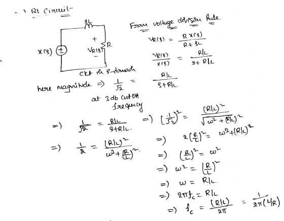
a. Show that series R-L circuits have a break frequency fRL = 1 / 2π (R/L) and the amplitude at the break point is 3db above the asymptotes
b. Show that series R-C circuits have a break frequency fRC= 1 / 2π (1/ RC) and the amplitude at the break point is 3db below the asymptotes
Homework Answers


Add Answer to:
1. Impedance versus frequency plots
a. Show that series R-L circuits have a break frequency
fRL...
2. Resonant circuits are employed in electrical engineering for narrow and broad band frequency selective filtering....
2. Resonant circuits are employed in electrical engineering for narrow and broad band frequency selective filtering. Impedance of R-L-C elements versus frequency is the understanding starting point, followed by R-L R-C and R-L-C circuits of various kinds. a. Plot the impedances ZL and ZC versus frequency on: 1. A linear impedance scale 2. A log impedance scale and show the slope versus frequency is 20 db per decade of frequency
1. Compute the impedance of a series R-L-C circuit at angular frequencies of ω1= 1000 rad/s...
1. Compute the impedance of a series R-L-C circuit at angular frequencies of ω1= 1000 rad/s , ω2= 710 rad/s and ω3= 455 rad/s . Take R = 170 Ω , L = 0.935 H and C = 2.40 μF . What is the phase angle of the source voltage with respect to the current when ω = 1000 rad/s? 2. A series R–L–C circuit of R = 150 Ω , L = 0.915 H and C = 2.05 μF...
Determine resonant frequency, amplitude, impedance, and phase angle. (b) Suppose the circuit parameters in a series...
 Determine resonant frequency, amplitude, impedance,
and phase angle.
(b) Suppose the circuit parameters in a series RLC circuit are: L = 1.0 uH, C = 10.0 nF, R= 10092, and the source voltage is 220 V. Determine the resonant frequency of the circuit and the amplitude of the current at resonance. If the frequency of the input voltage source is 50 Hz, calculate the impedance and the phase angle. f = 1 / 2 x 5c = 1/2 X 511...
Determine resonant frequency, amplitude, impedance,
and phase angle.
(b) Suppose the circuit parameters in a series RLC circuit are: L = 1.0 uH, C = 10.0 nF, R= 10092, and the source voltage is 220 V. Determine the resonant frequency of the circuit and the amplitude of the current at resonance. If the frequency of the input voltage source is 50 Hz, calculate the impedance and the phase angle. f = 1 / 2 x 5c = 1/2 X 511...
In the circuit below, the input voltage is Vin-Vinegakcos(wt), R-20 ΚΩandC15nFw l. in al Show that the output voltage is VotVcos (wt-), where V-V n peak/V1 + (RC) b) Show that this result justifies c...
 In the circuit below, the input voltage is Vin-Vinegakcos(wt), R-20 ΚΩandC15nFw l. in al Show that the output voltage is VotVcos (wt-), where V-V n peak/V1 + (RC) b) Show that this result justifies calling this circuit a high-pass filter+ c) Find an expression for the phase constant δ in terms of R,C and d) At what frequency is Vi (1/V2) Vin peak? That particular frequency is known as the 3dB frequency, or f3dB, of the circuit
In the circuit...
In the circuit below, the input voltage is Vin-Vinegakcos(wt), R-20 ΚΩandC15nFw l. in al Show that the output voltage is VotVcos (wt-), where V-V n peak/V1 + (RC) b) Show that this result justifies calling this circuit a high-pass filter+ c) Find an expression for the phase constant δ in terms of R,C and d) At what frequency is Vi (1/V2) Vin peak? That particular frequency is known as the 3dB frequency, or f3dB, of the circuit
In the circuit...
A series RLC network has R= 6 k1, L = 40 mH, and C= 1 uF....
 A series RLC network has R= 6 k1, L = 40 mH, and C= 1 uF. References eBook & Resources Section Break Difficulty: Medium value: 10.00 points Calculate the impedance at one-fourth of the resonant frequency. The impedance at one-fourth of the resonant frequency is + ke2
In the series RC circuit below, with R -6.1 k ohms& C 72.5 nF, at what angular frequency [rad/s] ...
 In the series RC circuit below, with R -6.1 k ohms& C 72.5 nF, at what angular frequency [rad/s] does the capacitor AC voltage reduce to its DC value (accurate to 1%)? C output Answer: In the series RC circuit below, with R-1.2 k ohms & C 92.8 nF, calculate the magnitude of the voltage 'gain' of the circuit (Vout/ Vsl), for a driving frequency of 0.1 kHz, to 1% accuracy. Coutput Answer For a series RLC circuit as shown...
Question 12 (1 point) In an L-R-C series circuit, L = 0.253 H, and C =...
 Question 12 (1 point) In an L-R-C series circuit, L = 0.253 H, and C = 4.02 ?F. The voltage amplitude of the source is 130 V. What is the resonance angular frequency of the circuit in rad/s?
1. From Figure 9-2 and the equations above choose which plot best describes the impedance due...
 1. From Figure 9-2 and the equations above choose which
plot best describes the impedance due to:
a. A Resistor
b. A Capacitor
PART 1: IMPEDANCE OF A CAPACITOR PREPARATION In an AC circuit capacitors and inductors have an effective resistance that restricts the flow of current, this is known as impedance. An equivalent to Ohm's law can be written where resistance R is replaced by the impedance Z: V = 12 (9-4) where V and I are either...
1. From Figure 9-2 and the equations above choose which
plot best describes the impedance due to:
a. A Resistor
b. A Capacitor
PART 1: IMPEDANCE OF A CAPACITOR PREPARATION In an AC circuit capacitors and inductors have an effective resistance that restricts the flow of current, this is known as impedance. An equivalent to Ohm's law can be written where resistance R is replaced by the impedance Z: V = 12 (9-4) where V and I are either...
Phasors and complex impedance 1. A resistor R and capacitor Care connected in series with an...
 Phasors and complex impedance 1. A resistor R and capacitor Care connected in series with an AC voltage source with frequency f and maximum voltage Vo. a. Find the complex impedance (in the form Z = R +jX). If the impedance is written in polar form (Z = Zej®), find expressions for Z and Ø. Write your answers in terms of the variables R, C, and (=21f). b. If the voltage source is described by the phasor V = V.ejut,...
A series RL circuit with L = 3.00 H and a series RC circuit with C...
A series RL circuit with L = 3.00 H and a series RC circuit with C = 3.00 F have equal time constants. If the two circuits contain the same resistances R, (a) what is the value of R and (b) what sit the time constant?
 Determine resonant frequency, amplitude, impedance,
and phase angle.
(b) Suppose the circuit parameters in a series RLC circuit are: L = 1.0 uH, C = 10.0 nF, R= 10092, and the source voltage is 220 V. Determine the resonant frequency of the circuit and the amplitude of the current at resonance. If the frequency of the input voltage source is 50 Hz, calculate the impedance and the phase angle. f = 1 / 2 x 5c = 1/2 X 511...
Determine resonant frequency, amplitude, impedance,
and phase angle.
(b) Suppose the circuit parameters in a series RLC circuit are: L = 1.0 uH, C = 10.0 nF, R= 10092, and the source voltage is 220 V. Determine the resonant frequency of the circuit and the amplitude of the current at resonance. If the frequency of the input voltage source is 50 Hz, calculate the impedance and the phase angle. f = 1 / 2 x 5c = 1/2 X 511...
 In the circuit below, the input voltage is Vin-Vinegakcos(wt), R-20 ΚΩandC15nFw l. in al Show that the output voltage is VotVcos (wt-), where V-V n peak/V1 + (RC) b) Show that this result justifies calling this circuit a high-pass filter+ c) Find an expression for the phase constant δ in terms of R,C and d) At what frequency is Vi (1/V2) Vin peak? That particular frequency is known as the 3dB frequency, or f3dB, of the circuit
In the circuit...
In the circuit below, the input voltage is Vin-Vinegakcos(wt), R-20 ΚΩandC15nFw l. in al Show that the output voltage is VotVcos (wt-), where V-V n peak/V1 + (RC) b) Show that this result justifies calling this circuit a high-pass filter+ c) Find an expression for the phase constant δ in terms of R,C and d) At what frequency is Vi (1/V2) Vin peak? That particular frequency is known as the 3dB frequency, or f3dB, of the circuit
In the circuit...
 A series RLC network has R= 6 k1, L = 40 mH, and C= 1 uF. References eBook & Resources Section Break Difficulty: Medium value: 10.00 points Calculate the impedance at one-fourth of the resonant frequency. The impedance at one-fourth of the resonant frequency is + ke2
 In the series RC circuit below, with R -6.1 k ohms& C 72.5 nF, at what angular frequency [rad/s] does the capacitor AC voltage reduce to its DC value (accurate to 1%)? C output Answer: In the series RC circuit below, with R-1.2 k ohms & C 92.8 nF, calculate the magnitude of the voltage 'gain' of the circuit (Vout/ Vsl), for a driving frequency of 0.1 kHz, to 1% accuracy. Coutput Answer For a series RLC circuit as shown...
 Question 12 (1 point) In an L-R-C series circuit, L = 0.253 H, and C = 4.02 ?F. The voltage amplitude of the source is 130 V. What is the resonance angular frequency of the circuit in rad/s?
 1. From Figure 9-2 and the equations above choose which
plot best describes the impedance due to:
a. A Resistor
b. A Capacitor
PART 1: IMPEDANCE OF A CAPACITOR PREPARATION In an AC circuit capacitors and inductors have an effective resistance that restricts the flow of current, this is known as impedance. An equivalent to Ohm's law can be written where resistance R is replaced by the impedance Z: V = 12 (9-4) where V and I are either...
1. From Figure 9-2 and the equations above choose which
plot best describes the impedance due to:
a. A Resistor
b. A Capacitor
PART 1: IMPEDANCE OF A CAPACITOR PREPARATION In an AC circuit capacitors and inductors have an effective resistance that restricts the flow of current, this is known as impedance. An equivalent to Ohm's law can be written where resistance R is replaced by the impedance Z: V = 12 (9-4) where V and I are either...
 Phasors and complex impedance 1. A resistor R and capacitor Care connected in series with an AC voltage source with frequency f and maximum voltage Vo. a. Find the complex impedance (in the form Z = R +jX). If the impedance is written in polar form (Z = Zej®), find expressions for Z and Ø. Write your answers in terms of the variables R, C, and (=21f). b. If the voltage source is described by the phasor V = V.ejut,...
Most questions answered within 3 hours.
-
Where is the error in this code sequence?
String s1 = "Hello";
String s2 = "ello";...
asked 10 months ago -
Financial data for Joel de Paris, Inc., for last year
follow:
Joel de Paris, Inc.
Balance...
asked 10 months ago -
Consider this reaction:
Al2(SO4)3 (aq)+ BaCl3
(aq) Al2Cl6 (aq)- +
3BaSO4(s) . What is the...
asked 10 months ago -
Suppose that Savneet is considering increasing her
recent random sample from 20 car rentals to 40...
asked 10 months ago -
Trucks arrive at an unloading terminal at an average rate of 120
per hour.
Trucks arrive...
asked 10 months ago -
Why are methanol and ethanol completely soluble in water while
octanol is not very little soluble....
asked 10 months ago -
A facilities manager at a university reads in a research report
that the mean amount of...
asked 10 months ago -
When the CuSO4 is rehydrated by adding water to the anhydrous
compound, is this an endothermic...
asked 10 months ago -
A ray of sunlight is passing from diamond into crown glass; the
angle of incidence is...
asked 10 months ago -
A block of mass 0.249 kg is placed on top of a light, vertical
spring of...
asked 10 months ago -
how do the kidneys compensate in the presences of acidosis
a) trigger hyperventilate
b) reserve acid...
asked 10 months ago -
Question 501 pts
The rental rate of capital to the firm increases. Which of the
following...
asked 10 months ago