
Homework Answers

Add Answer to:
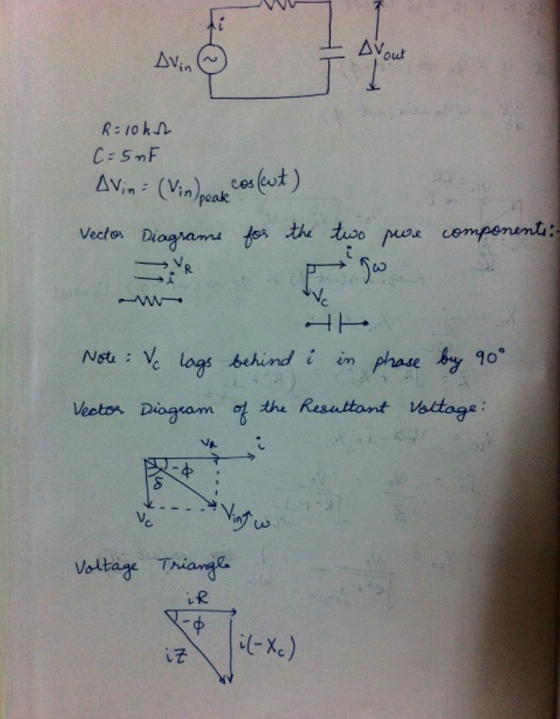
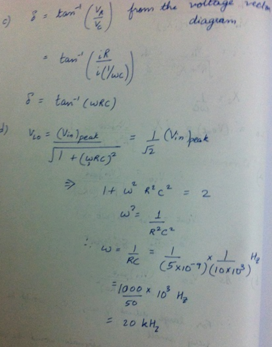
In the circuit below, the input voltage is Vin-Vinegakcos(wt), R-20 ΚΩandC15nFw l. in al Show that the output voltage is VotVcos (wt-), where V-V n peak/V1 + (RC) b) Show that this result justifies c...
5) Consider the following second-order bandpass filter. As input voltage, apply V(t) 100Ω, C-4.7 μF. and L-10mH. sin(wt).R in Vout Fig 9: Second-order band-pass filter a) Determine the frequenc...
 5) Consider the following second-order bandpass filter. As input voltage, apply V(t) 100Ω, C-4.7 μF. and L-10mH. sin(wt).R in Vout Fig 9: Second-order band-pass filter a) Determine the frequency response function H(ju) Ve-ju) / Vm(ju) and sketch the magnitude and phase characteristics versus w by calaulation. Calculate the theoretical cutoff frequency of the filter Using PSpice AC analysis, plot magnitude lHju)l and phase ф characteristics of the filter, between 1 Hz-100 KHz b) c)
5) Consider the following second-order bandpass...
5) Consider the following second-order bandpass filter. As input voltage, apply V(t) 100Ω, C-4.7 μF. and L-10mH. sin(wt).R in Vout Fig 9: Second-order band-pass filter a) Determine the frequency response function H(ju) Ve-ju) / Vm(ju) and sketch the magnitude and phase characteristics versus w by calaulation. Calculate the theoretical cutoff frequency of the filter Using PSpice AC analysis, plot magnitude lHju)l and phase ф characteristics of the filter, between 1 Hz-100 KHz b) c)
5) Consider the following second-order bandpass...
Q.6 For the series circuit in Figure given below, Determine Assume R -500n Vin-10V . The center frequency (f) b. The output voltage magnitude at (f) c. The bandwidth (BW )for the filter d. Draw t...
 Q.6 For the series circuit in Figure given below, Determine Assume R -500n Vin-10V . The center frequency (f) b. The output voltage magnitude at (f) c. The bandwidth (BW )for the filter d. Draw the output response curve showing the maximum voltage, center frequency and the voltage where the BW is measured 150Ω 100μH
Q.6 For the series circuit in Figure given below, Determine Assume R -500n Vin-10V . The center frequency (f) b. The output voltage magnitude at...
Q.6 For the series circuit in Figure given below, Determine Assume R -500n Vin-10V . The center frequency (f) b. The output voltage magnitude at (f) c. The bandwidth (BW )for the filter d. Draw the output response curve showing the maximum voltage, center frequency and the voltage where the BW is measured 150Ω 100μH
Q.6 For the series circuit in Figure given below, Determine Assume R -500n Vin-10V . The center frequency (f) b. The output voltage magnitude at...
Consider the circuit below, where R-5000Ω,C-0.25μF . The voltage amplitude is 10 V and the frequency...
 Consider the circuit below, where R-5000Ω,C-0.25μF . The voltage amplitude is 10 V and the frequency of oscillation is 180 rad Is . When voltages and currents are requested, express them in purely real terms. Note: this circuit is examined in some detail in Chapter 7, section 2. Have a look at that first. a) What is the total impedance? Express it as both a complex number and as magnitude and phase. What is the current in the circuit? What...
A common source amplifier circuit based on a single n-channel MOSFET is shown in Figure 4b. Assume that the transconductance gm-60 mS (equivalent to mA/ V) and drain source resistance, os,...
 A common source amplifier circuit based on a single n-channel MOSFET is shown in Figure 4b. Assume that the transconductance gm-60 mS (equivalent to mA/ V) and drain source resistance, os, is so large it may be neglected. 0) Calculate the open circuit voltage gain Av Yout/ Vis. i) The amplifier has a load of 10 k2. Determine the current gain Va. = 12 V 150k 4k3 Vout Vin 200k GND = 0 V Figure 4b a) State the name...
Vout should be a sinusoid signal of 12Vp-p Dc voltage to uA741 : +/-8.5V Please simulate...
 Vout should be a sinusoid signal of 12Vp-p
Dc voltage to uA741 : +/-8.5V
Please simulate as well
please help, im completely lost on this
this is all of the information
Experiment 5. RC Sinusoidal Oscillators PURPOSE: This laboratory provides an introduction to the background, analysis and design of sinusoidal oscillators using RC feedback networks and active devices to achieve the criteria for continuous oscillations to occur. EQUIPMENT REQUIRED : 1 Operational amplifier u.A741 1 CEU development station Resistors and...
Vout should be a sinusoid signal of 12Vp-p
Dc voltage to uA741 : +/-8.5V
Please simulate as well
please help, im completely lost on this
this is all of the information
Experiment 5. RC Sinusoidal Oscillators PURPOSE: This laboratory provides an introduction to the background, analysis and design of sinusoidal oscillators using RC feedback networks and active devices to achieve the criteria for continuous oscillations to occur. EQUIPMENT REQUIRED : 1 Operational amplifier u.A741 1 CEU development station Resistors and...
 5) Consider the following second-order bandpass filter. As input voltage, apply V(t) 100Ω, C-4.7 μF. and L-10mH. sin(wt).R in Vout Fig 9: Second-order band-pass filter a) Determine the frequency response function H(ju) Ve-ju) / Vm(ju) and sketch the magnitude and phase characteristics versus w by calaulation. Calculate the theoretical cutoff frequency of the filter Using PSpice AC analysis, plot magnitude lHju)l and phase ф characteristics of the filter, between 1 Hz-100 KHz b) c)
5) Consider the following second-order bandpass...
5) Consider the following second-order bandpass filter. As input voltage, apply V(t) 100Ω, C-4.7 μF. and L-10mH. sin(wt).R in Vout Fig 9: Second-order band-pass filter a) Determine the frequency response function H(ju) Ve-ju) / Vm(ju) and sketch the magnitude and phase characteristics versus w by calaulation. Calculate the theoretical cutoff frequency of the filter Using PSpice AC analysis, plot magnitude lHju)l and phase ф characteristics of the filter, between 1 Hz-100 KHz b) c)
5) Consider the following second-order bandpass...
 Q.6 For the series circuit in Figure given below, Determine Assume R -500n Vin-10V . The center frequency (f) b. The output voltage magnitude at (f) c. The bandwidth (BW )for the filter d. Draw the output response curve showing the maximum voltage, center frequency and the voltage where the BW is measured 150Ω 100μH
Q.6 For the series circuit in Figure given below, Determine Assume R -500n Vin-10V . The center frequency (f) b. The output voltage magnitude at...
Q.6 For the series circuit in Figure given below, Determine Assume R -500n Vin-10V . The center frequency (f) b. The output voltage magnitude at (f) c. The bandwidth (BW )for the filter d. Draw the output response curve showing the maximum voltage, center frequency and the voltage where the BW is measured 150Ω 100μH
Q.6 For the series circuit in Figure given below, Determine Assume R -500n Vin-10V . The center frequency (f) b. The output voltage magnitude at...
 Consider the circuit below, where R-5000Ω,C-0.25μF . The voltage amplitude is 10 V and the frequency of oscillation is 180 rad Is . When voltages and currents are requested, express them in purely real terms. Note: this circuit is examined in some detail in Chapter 7, section 2. Have a look at that first. a) What is the total impedance? Express it as both a complex number and as magnitude and phase. What is the current in the circuit? What...
 A common source amplifier circuit based on a single n-channel MOSFET is shown in Figure 4b. Assume that the transconductance gm-60 mS (equivalent to mA/ V) and drain source resistance, os, is so large it may be neglected. 0) Calculate the open circuit voltage gain Av Yout/ Vis. i) The amplifier has a load of 10 k2. Determine the current gain Va. = 12 V 150k 4k3 Vout Vin 200k GND = 0 V Figure 4b a) State the name...
 Vout should be a sinusoid signal of 12Vp-p
Dc voltage to uA741 : +/-8.5V
Please simulate as well
please help, im completely lost on this
this is all of the information
Experiment 5. RC Sinusoidal Oscillators PURPOSE: This laboratory provides an introduction to the background, analysis and design of sinusoidal oscillators using RC feedback networks and active devices to achieve the criteria for continuous oscillations to occur. EQUIPMENT REQUIRED : 1 Operational amplifier u.A741 1 CEU development station Resistors and...
Vout should be a sinusoid signal of 12Vp-p
Dc voltage to uA741 : +/-8.5V
Please simulate as well
please help, im completely lost on this
this is all of the information
Experiment 5. RC Sinusoidal Oscillators PURPOSE: This laboratory provides an introduction to the background, analysis and design of sinusoidal oscillators using RC feedback networks and active devices to achieve the criteria for continuous oscillations to occur. EQUIPMENT REQUIRED : 1 Operational amplifier u.A741 1 CEU development station Resistors and...
Most questions answered within 3 hours.
-
Where is the error in this code sequence?
String s1 = "Hello";
String s2 = "ello";...
asked 10 months ago -
Financial data for Joel de Paris, Inc., for last year
follow:
Joel de Paris, Inc.
Balance...
asked 10 months ago -
Consider this reaction:
Al2(SO4)3 (aq)+ BaCl3
(aq) Al2Cl6 (aq)- +
3BaSO4(s) . What is the...
asked 10 months ago -
Suppose that Savneet is considering increasing her
recent random sample from 20 car rentals to 40...
asked 10 months ago -
Trucks arrive at an unloading terminal at an average rate of 120
per hour.
Trucks arrive...
asked 10 months ago -
Why are methanol and ethanol completely soluble in water while
octanol is not very little soluble....
asked 10 months ago -
A facilities manager at a university reads in a research report
that the mean amount of...
asked 10 months ago -
When the CuSO4 is rehydrated by adding water to the anhydrous
compound, is this an endothermic...
asked 10 months ago -
A ray of sunlight is passing from diamond into crown glass; the
angle of incidence is...
asked 10 months ago -
A block of mass 0.249 kg is placed on top of a light, vertical
spring of...
asked 10 months ago -
how do the kidneys compensate in the presences of acidosis
a) trigger hyperventilate
b) reserve acid...
asked 10 months ago -
Question 501 pts
The rental rate of capital to the firm increases. Which of the
following...
asked 10 months ago