
Homework Answers

Add Answer to:
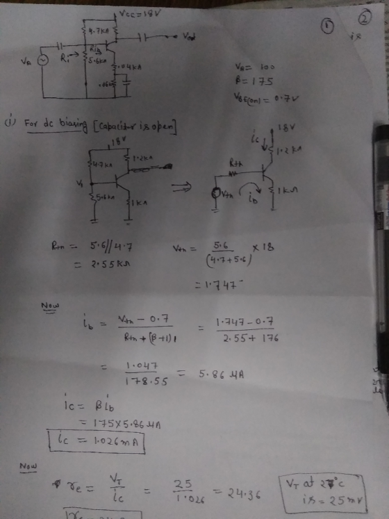
#3. Given the amplifier configuration shown below where B 175 and, VA 100 VBE(o)-0.7V. Find the...
0.7V, and Va 100V. Find: -For the operational amplifier of Figure 4 assume all transistors have β...
 0.7V, and Va 100V. Find: -For the operational amplifier of Figure 4 assume all transistors have β-100, Find the de emitter currents and the de collector voltage of all transistors. The de voltage at the inputs is OV and the de output voltage is held at 0V (by negative feedback, not shown). Neglect the de base currents for this part. Find the (differential) voltage gain of the amplifier with R-10 k2. Assume the impedance of the capacitor is very large....
4. For the amplifier in the figure below use the parameters in the table: +Vcc Re VBE- 0.7V, Ri- ...
 4. For the amplifier in the figure below use the parameters in the table: +Vcc Re VBE- 0.7V, Ri- 1002, R1-160k2, R2-320k2 R3-200k2, R6-40 k2, Rc-60k2, Vcc- 12V, Ry Do a) Draw the DC equivalent circuit and calculate the Q-point. c) Draw the AC equivalent circuit with the small signal model for the transistor. d) Calculate the voltage gain, Av-Vo/vi. Assume ro infinite. e) Draw the circuit to find the amplifier input resistance (Rin). Calculate Rin f Draw the circuit...
The amplifier circuit that is given in form-3, is B = 100, C o, VT =...
 The amplifier circuit that is given in form-3, is B = 100, C o, VT = 25.845mV, VBE = VEB = 0.7V; calculate the values of re1, re2 and Av = ( vo / vsig). (ro values will be neglected.) Vcc= 10 10.5mA R <10k 2 С RE Q1 10k92 Vsig + VEB=0
For the circuit shown below, let Vcc 9 V R2 RE-0.11 kQ, R1 3.6 k2. and R2 -5.6 kQ. The transistor parameters are β-200, VBE(on)-OTV, VA-100 V and VT = 0.026 V. (a) Determine the quiescent value o...
 For the circuit shown below, let Vcc 9 V R2 RE-0.11 kQ, R1 3.6 k2. and R2 -5.6 kQ. The transistor parameters are β-200, VBE(on)-OTV, VA-100 V and VT = 0.026 V. (a) Determine the quiescent value of IEQ (b) Find the small-signal voltage gain Av Vo/vs (c) Determine the output resistance R, looking into output terminals Av= 0.5589 Ro-0.4688 Ω Ro-0.9118 Ω leQ- 23.76 mA Ra " 0.6538 Ω leo 39.52 mA A, 0.9938
For the circuit shown below,...
For the circuit shown below, let Vcc 9 V R2 RE-0.11 kQ, R1 3.6 k2. and R2 -5.6 kQ. The transistor parameters are β-200, VBE(on)-OTV, VA-100 V and VT = 0.026 V. (a) Determine the quiescent value of IEQ (b) Find the small-signal voltage gain Av Vo/vs (c) Determine the output resistance R, looking into output terminals Av= 0.5589 Ro-0.4688 Ω Ro-0.9118 Ω leQ- 23.76 mA Ra " 0.6538 Ω leo 39.52 mA A, 0.9938
For the circuit shown below,...
0.7V, and Va 100V. Find: -For the operational amplifier of Figure 4 assume all transistors have...
 0.7V, and Va 100V. Find: -For the operational amplifier of Figure 4 assume all transistors have β-100, Find the de emitter currents and the de collector voltage of all transistors. The de voltage at the inputs is OV and the de output voltage is held at 0V (by negative feedback, not shown). Neglect the de base currents for this part. Find the (differential) voltage gain of the amplifier with R-10 k2. Assume the impedance of the capacitor is very large....
In the CE amplifier shown below, a. Find the transistor DC operating points. Check what region...
 In the CE amplifier shown below, a. Find the transistor DC operating points. Check what region of operation the transistor is biased at. b. Calculate the small signal voltage gain, the input resistance looking into the base of the transistor, and the output resistance looking down at the collector. c. Find the small signal current gain, 으 VBE,ON = 0.6V, and β = 100, VA = 00, Base current may be ignored if possible
(b) Refer to Figure Q5.2, given VBE = 0.6V, ro infinit re V.2, given VBE =...
 (b) Refer to Figure Q5.2, given VBE = 0.6V, ro infinit re V.2, given VBE = 0.6V, ro infinity and thermal voltage of 26 mV, draw the ac equivalent circuit and calculate: (i) Input impedance, Zin (ii) Output impedance, Zout (iii) Gain, Av. (13 Marks) (PO3/C03/C4) Ic(mA) - lg = 400 UA RB w taylo = 300 UA 30++ - +/Vcc is --V-18 = 200 A Vin Bpc = 100 VBB 3.7 V Figure Q5.2
4. Consider the BJT cascade amplifier shown below Vcc 18V R1 3.3ko 15uF r Vo RL...
 4. Consider the BJT cascade amplifier shown below Vcc 18V R1 3.3ko 15uF r Vo RL B 150 Rsa 500? 56k? Vi B 150 C1 CE 2.2k? a) Find the DC collector current (approximately the same in both transistors). b) Find the input impedance, output impedance, and no-load voltage gain. c) Find the Av, Avs, and Ai d) Estimate the lower cutoff frequency e) Why does this amplifier have better high-frequency performance thana common-emitter built using the same type of...
Problem 2. T Vcc=10v 4R3 Rc=5k12 Ko Yout C=0 Q(8=100, VBE=0.7, V=25mV, VA ) IRB IC=0...
 Problem 2. T Vcc=10v 4R3 Rc=5k12 Ko Yout C=0 Q(8=100, VBE=0.7, V=25mV, VA ) IRB IC=0 RB Fig. 3 In the common emitter amplifier shown in Fig. 3. a) Neglecting the base current (18 = 0), determine Rei and Rez to set Ice = 1 mA and the small-signal voltage gain |Apl= |Vout/Vin) = 20. [45 pt.) b) Base on the Ico given and ß = 100, choose Rp so that lg is 5% of IRB (15 pt.)
An amplifier circuit is shown in Fig. 1b. The operational amplifier (op-amp) Ai can be assumed...
 An amplifier circuit is shown in Fig. 1b. The operational amplifier (op-amp) Ai can be assumed as ideal. The input impedance of this amplifier is 1M2. The gain of this amplifier is -100. R2 V R VVV 小小 Ri Fig. 1b (a) Show that 12 = (b) Find the expression of the voltage gain, Av, in terms Ri, R, R3 and R4. (c) Due to practical reasons, the maximum value to be used for the resistors is set at 1M2....
 0.7V, and Va 100V. Find: -For the operational amplifier of Figure 4 assume all transistors have β-100, Find the de emitter currents and the de collector voltage of all transistors. The de voltage at the inputs is OV and the de output voltage is held at 0V (by negative feedback, not shown). Neglect the de base currents for this part. Find the (differential) voltage gain of the amplifier with R-10 k2. Assume the impedance of the capacitor is very large....
 4. For the amplifier in the figure below use the parameters in the table: +Vcc Re VBE- 0.7V, Ri- 1002, R1-160k2, R2-320k2 R3-200k2, R6-40 k2, Rc-60k2, Vcc- 12V, Ry Do a) Draw the DC equivalent circuit and calculate the Q-point. c) Draw the AC equivalent circuit with the small signal model for the transistor. d) Calculate the voltage gain, Av-Vo/vi. Assume ro infinite. e) Draw the circuit to find the amplifier input resistance (Rin). Calculate Rin f Draw the circuit...
 The amplifier circuit that is given in form-3, is B = 100, C o, VT = 25.845mV, VBE = VEB = 0.7V; calculate the values of re1, re2 and Av = ( vo / vsig). (ro values will be neglected.) Vcc= 10 10.5mA R <10k 2 С RE Q1 10k92 Vsig + VEB=0
 For the circuit shown below, let Vcc 9 V R2 RE-0.11 kQ, R1 3.6 k2. and R2 -5.6 kQ. The transistor parameters are β-200, VBE(on)-OTV, VA-100 V and VT = 0.026 V. (a) Determine the quiescent value of IEQ (b) Find the small-signal voltage gain Av Vo/vs (c) Determine the output resistance R, looking into output terminals Av= 0.5589 Ro-0.4688 Ω Ro-0.9118 Ω leQ- 23.76 mA Ra " 0.6538 Ω leo 39.52 mA A, 0.9938
For the circuit shown below,...
For the circuit shown below, let Vcc 9 V R2 RE-0.11 kQ, R1 3.6 k2. and R2 -5.6 kQ. The transistor parameters are β-200, VBE(on)-OTV, VA-100 V and VT = 0.026 V. (a) Determine the quiescent value of IEQ (b) Find the small-signal voltage gain Av Vo/vs (c) Determine the output resistance R, looking into output terminals Av= 0.5589 Ro-0.4688 Ω Ro-0.9118 Ω leQ- 23.76 mA Ra " 0.6538 Ω leo 39.52 mA A, 0.9938
For the circuit shown below,...
 0.7V, and Va 100V. Find: -For the operational amplifier of Figure 4 assume all transistors have β-100, Find the de emitter currents and the de collector voltage of all transistors. The de voltage at the inputs is OV and the de output voltage is held at 0V (by negative feedback, not shown). Neglect the de base currents for this part. Find the (differential) voltage gain of the amplifier with R-10 k2. Assume the impedance of the capacitor is very large....
 In the CE amplifier shown below, a. Find the transistor DC operating points. Check what region of operation the transistor is biased at. b. Calculate the small signal voltage gain, the input resistance looking into the base of the transistor, and the output resistance looking down at the collector. c. Find the small signal current gain, 으 VBE,ON = 0.6V, and β = 100, VA = 00, Base current may be ignored if possible
 (b) Refer to Figure Q5.2, given VBE = 0.6V, ro infinit re V.2, given VBE = 0.6V, ro infinity and thermal voltage of 26 mV, draw the ac equivalent circuit and calculate: (i) Input impedance, Zin (ii) Output impedance, Zout (iii) Gain, Av. (13 Marks) (PO3/C03/C4) Ic(mA) - lg = 400 UA RB w taylo = 300 UA 30++ - +/Vcc is --V-18 = 200 A Vin Bpc = 100 VBB 3.7 V Figure Q5.2
 4. Consider the BJT cascade amplifier shown below Vcc 18V R1 3.3ko 15uF r Vo RL B 150 Rsa 500? 56k? Vi B 150 C1 CE 2.2k? a) Find the DC collector current (approximately the same in both transistors). b) Find the input impedance, output impedance, and no-load voltage gain. c) Find the Av, Avs, and Ai d) Estimate the lower cutoff frequency e) Why does this amplifier have better high-frequency performance thana common-emitter built using the same type of...
 Problem 2. T Vcc=10v 4R3 Rc=5k12 Ko Yout C=0 Q(8=100, VBE=0.7, V=25mV, VA ) IRB IC=0 RB Fig. 3 In the common emitter amplifier shown in Fig. 3. a) Neglecting the base current (18 = 0), determine Rei and Rez to set Ice = 1 mA and the small-signal voltage gain |Apl= |Vout/Vin) = 20. [45 pt.) b) Base on the Ico given and ß = 100, choose Rp so that lg is 5% of IRB (15 pt.)
 An amplifier circuit is shown in Fig. 1b. The operational amplifier (op-amp) Ai can be assumed as ideal. The input impedance of this amplifier is 1M2. The gain of this amplifier is -100. R2 V R VVV 小小 Ri Fig. 1b (a) Show that 12 = (b) Find the expression of the voltage gain, Av, in terms Ri, R, R3 and R4. (c) Due to practical reasons, the maximum value to be used for the resistors is set at 1M2....
Most questions answered within 3 hours.
-
Where is the error in this code sequence?
String s1 = "Hello";
String s2 = "ello";...
asked 10 months ago -
Financial data for Joel de Paris, Inc., for last year
follow:
Joel de Paris, Inc.
Balance...
asked 10 months ago -
Consider this reaction:
Al2(SO4)3 (aq)+ BaCl3
(aq) Al2Cl6 (aq)- +
3BaSO4(s) . What is the...
asked 10 months ago -
Suppose that Savneet is considering increasing her
recent random sample from 20 car rentals to 40...
asked 10 months ago -
Trucks arrive at an unloading terminal at an average rate of 120
per hour.
Trucks arrive...
asked 10 months ago -
Why are methanol and ethanol completely soluble in water while
octanol is not very little soluble....
asked 10 months ago -
A facilities manager at a university reads in a research report
that the mean amount of...
asked 10 months ago -
When the CuSO4 is rehydrated by adding water to the anhydrous
compound, is this an endothermic...
asked 10 months ago -
A ray of sunlight is passing from diamond into crown glass; the
angle of incidence is...
asked 10 months ago -
A block of mass 0.249 kg is placed on top of a light, vertical
spring of...
asked 10 months ago -
how do the kidneys compensate in the presences of acidosis
a) trigger hyperventilate
b) reserve acid...
asked 10 months ago -
Question 501 pts
The rental rate of capital to the firm increases. Which of the
following...
asked 10 months ago