
Homework Answers
Add Answer to:
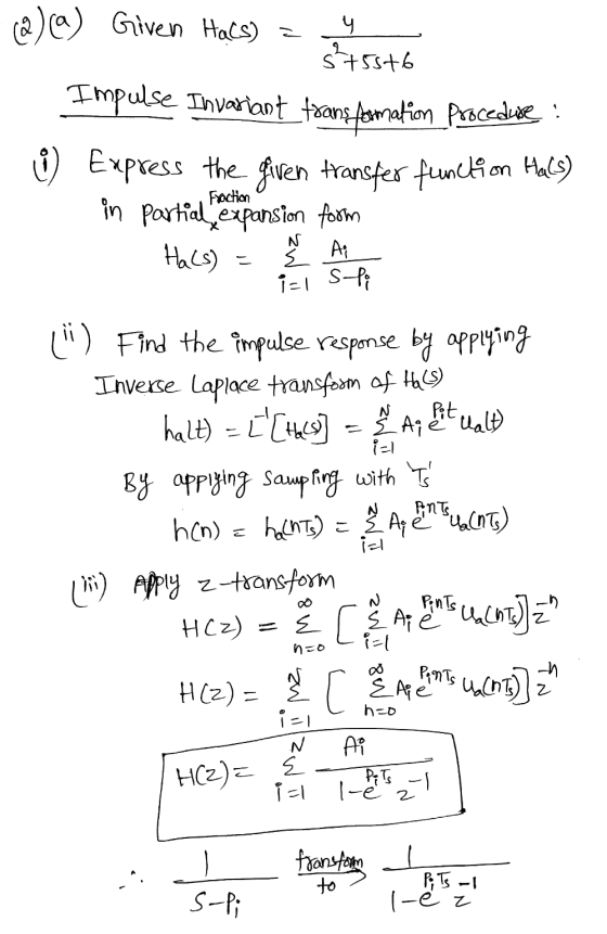
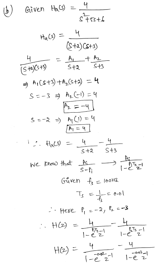
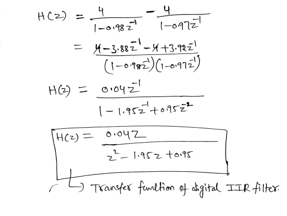
2. (50 marks) Consider using the impulse invariance method to design a prototype IIR digital filter...
6. (20 points) (1) Design an analog lowpass filter with a cut-off frequency of 9 rad/sec by starting with an analogue prototype first-order lowpass filter with cut-off frequency of 1 rad/sec. Sho...
 6. (20 points) (1) Design an analog lowpass filter with a cut-off frequency of 9 rad/sec by starting with an analogue prototype first-order lowpass filter with cut-off frequency of 1 rad/sec. Show the system transfer function H(s) (2) Design an IIR digital filter Hz) that corresponds to the above H(s) by using the bilinear transform method without prewarping with T 0.1 second. Show the system transfer function Hz) and find its corresponding digital cut-off frequency Be approximately (3) What is...
QUESTION 6 Зро Design a second-order IIR digital low-pass filter using Butterworth approximation....
 QUESTION 6 Зро Design a second-order IIR digital low-pass filter using Butterworth approximation. Use the bilinear transformation to convert the analogue fiter to a digital one (choose the sampling period T- 2 s and the cut-off frequency as 1 rad/'s). Express the digital transfer function of the filter H(z) as: In the box below, provide the numerical answer for b1. [Note: Don't normalise the transfer func on, i.e. b0 # 1). r98111acontentid1837836_1&step QUESTION 7 Windowing based FIR filter design techniques...
Using filterDesigner in MATLAB, design a second order low pass IIR Butterworth filter whose sampling frequency...
Using filterDesigner in MATLAB, design a second order low pass IIR Butterworth filter whose sampling frequency (Fs) is 1 kHz and cutoff frequency (Fc) is 10 Hz. Find the numerator and denominator coefficients. Write its transfer function H(z) = Y(z) / X(z). Write its difference function y(k). Draw (copy from Filter Designer) the magnitude response plot. Draw (copy from Filter Designer) the phase response plot. Draw (copy from Filter Designer) the impulse response plot.
Using filterDesigner in MATLAB, design a second order low pass IIR Butterworth filter whose sampling frequency (Fs) is 1...
Using filterDesigner in MATLAB, design a second order low pass IIR Butterworth filter whose sampling frequency (Fs) is 1 kHz and cutoff frequency (Fc) is 10 Hz. Find the numerator and denominator coefficients. Write its transfer function H(z) = Y(z) / X(z). Write its difference function y(k). Draw (copy from Filter Designer) the magnitude response plot. Draw (copy from Filter Designer) the phase response plot. Draw (copy from Filter Designer) the impulse response plot.
Question 2. (25 marks) Design a discrete time low-pass IIR filter operating at a sampling rate of 8 kHz such that its magnitude response is monotonic (i.e., smooth with no ripples) and satisfies the...
 Question 2. (25 marks) Design a discrete time low-pass IIR filter operating at a sampling rate of 8 kHz such that its magnitude response is monotonic (i.e., smooth with no ripples) and satisfies the following conditions (i) The magnitude response has an attenuation of at least 20dB at 2000 Hz (ii) The magnitude response has an attenuation of at most 2dB at 1000 Hz Determine the transfer function, H(z) A. 120 Marks] sketch the Direct Form II structure of the...
Design a second order IIR Butterworth low pass digital filter with a cutoff frequency of 500...
Design a second order IIR Butterworth low pass digital filter with a cutoff frequency of 500 Hz and a sampling frequency of 10,000 Hz using bilinear transformation then find the following: The output (response) due to the following inputs: Sinusoidal signal with a frequency of 100Hz. Sinusoidal signal with a frequency of 500Hz. Sinusoidal signal with a frequency of 2000Hz. Repeat (a) above for a 6thorder Butterworth filter
Design lowpass IIR filter with the following specifications: Filter order = 2, Butterworth type C...
Design lowpass IIR filter with the following specifications: Filter order = 2, Butterworth type Cut-off frequency=800 Hz Sampling rate =8000 Hz Design using the bilinear z-transform design method Print the lowpass IIR filter coefficients and plot the frequency responses using MATLAB. MATLAB>>freqz(bLP,aLP,512,8000); axis([0 4000 –40 1]); Label and print your graph. What is the filter gain at the cut-off frequency 800 Hz? What are the filter gains for the stopband at 2000 Hz and the passband at 50 Hz based...
1. By using an analog filter with a Butterworth response of order 3, design a digital IIR low pass filter with 3-db cutoff frequency 2c 0.6TT a) b) c) Evaluate the transfer function of the analog fil...
 1. By using an analog filter with a Butterworth response of order 3, design a digital IIR low pass filter with 3-db cutoff frequency 2c 0.6TT a) b) c) Evaluate the transfer function of the analog filter (10marks) Skecth the block diagram of transfer function (5 marks) Plot the magnitude response of the filters. (5marks)
1. By using an analog filter with a Butterworth response of order 3, design a digital IIR low pass filter with 3-db cutoff frequency 2c...
1. By using an analog filter with a Butterworth response of order 3, design a digital IIR low pass filter with 3-db cutoff frequency 2c 0.6TT a) b) c) Evaluate the transfer function of the analog filter (10marks) Skecth the block diagram of transfer function (5 marks) Plot the magnitude response of the filters. (5marks)
1. By using an analog filter with a Butterworth response of order 3, design a digital IIR low pass filter with 3-db cutoff frequency 2c...
Please solve these questions. Thank you. 16.3 (a) Use the impulse invariance method to show that...
 Please solve these questions. Thank you.
16.3 (a) Use the impulse invariance method to show that the analog transfer function given by 2.6702 H(s)=3+2.7747s2 +3.8494s +2.6702 B. Friedlander and B. Porat, the modified Yule-Walker method of ARMA spectral estimation, IEEE Transactions on Aerospace Electronic Systems (1984), AES-20(2), 158-173. (2] L. B. Jackson, Digital Filters and Signal Processing. 3rd edn. Kluwer Academic Publishers (1996), Chap. 10, pp. 345-355 16 lIR filter design results in the following z-transfer function: 0.4695220.1907z H(z)=3-0.610622 +0.3398z-...
Please solve these questions. Thank you.
16.3 (a) Use the impulse invariance method to show that the analog transfer function given by 2.6702 H(s)=3+2.7747s2 +3.8494s +2.6702 B. Friedlander and B. Porat, the modified Yule-Walker method of ARMA spectral estimation, IEEE Transactions on Aerospace Electronic Systems (1984), AES-20(2), 158-173. (2] L. B. Jackson, Digital Filters and Signal Processing. 3rd edn. Kluwer Academic Publishers (1996), Chap. 10, pp. 345-355 16 lIR filter design results in the following z-transfer function: 0.4695220.1907z H(z)=3-0.610622 +0.3398z-...
Discrete Time Signal Processing Question 1. Consider an IIR filter A(1-2-1 cos ω0) 1-2cos ω02-1+2...
 Discrete Time Signal Processing Question 1. Consider an IIR filter A(1-2-1 cos ω0) 1-2cos ω02-1+2 I. Compute its impulse response using the difference equation with an impulse signal δ(n) as the input. Use trigonometric identities to simplify the result as much as you can 2. Draw the diagram showing the implementation of this filter in terms of adders, delays and multipliers Note: The IIR filter above generates a cosinusoidal signal when an impulse signal is applied at its input.] Question...
 6. (20 points) (1) Design an analog lowpass filter with a cut-off frequency of 9 rad/sec by starting with an analogue prototype first-order lowpass filter with cut-off frequency of 1 rad/sec. Show the system transfer function H(s) (2) Design an IIR digital filter Hz) that corresponds to the above H(s) by using the bilinear transform method without prewarping with T 0.1 second. Show the system transfer function Hz) and find its corresponding digital cut-off frequency Be approximately (3) What is...
 QUESTION 6 Зро Design a second-order IIR digital low-pass filter using Butterworth approximation. Use the bilinear transformation to convert the analogue fiter to a digital one (choose the sampling period T- 2 s and the cut-off frequency as 1 rad/'s). Express the digital transfer function of the filter H(z) as: In the box below, provide the numerical answer for b1. [Note: Don't normalise the transfer func on, i.e. b0 # 1). r98111acontentid1837836_1&step QUESTION 7 Windowing based FIR filter design techniques...
 Question 2. (25 marks) Design a discrete time low-pass IIR filter operating at a sampling rate of 8 kHz such that its magnitude response is monotonic (i.e., smooth with no ripples) and satisfies the following conditions (i) The magnitude response has an attenuation of at least 20dB at 2000 Hz (ii) The magnitude response has an attenuation of at most 2dB at 1000 Hz Determine the transfer function, H(z) A. 120 Marks] sketch the Direct Form II structure of the...
 1. By using an analog filter with a Butterworth response of order 3, design a digital IIR low pass filter with 3-db cutoff frequency 2c 0.6TT a) b) c) Evaluate the transfer function of the analog filter (10marks) Skecth the block diagram of transfer function (5 marks) Plot the magnitude response of the filters. (5marks)
1. By using an analog filter with a Butterworth response of order 3, design a digital IIR low pass filter with 3-db cutoff frequency 2c...
1. By using an analog filter with a Butterworth response of order 3, design a digital IIR low pass filter with 3-db cutoff frequency 2c 0.6TT a) b) c) Evaluate the transfer function of the analog filter (10marks) Skecth the block diagram of transfer function (5 marks) Plot the magnitude response of the filters. (5marks)
1. By using an analog filter with a Butterworth response of order 3, design a digital IIR low pass filter with 3-db cutoff frequency 2c...
 Please solve these questions. Thank you.
16.3 (a) Use the impulse invariance method to show that the analog transfer function given by 2.6702 H(s)=3+2.7747s2 +3.8494s +2.6702 B. Friedlander and B. Porat, the modified Yule-Walker method of ARMA spectral estimation, IEEE Transactions on Aerospace Electronic Systems (1984), AES-20(2), 158-173. (2] L. B. Jackson, Digital Filters and Signal Processing. 3rd edn. Kluwer Academic Publishers (1996), Chap. 10, pp. 345-355 16 lIR filter design results in the following z-transfer function: 0.4695220.1907z H(z)=3-0.610622 +0.3398z-...
Please solve these questions. Thank you.
16.3 (a) Use the impulse invariance method to show that the analog transfer function given by 2.6702 H(s)=3+2.7747s2 +3.8494s +2.6702 B. Friedlander and B. Porat, the modified Yule-Walker method of ARMA spectral estimation, IEEE Transactions on Aerospace Electronic Systems (1984), AES-20(2), 158-173. (2] L. B. Jackson, Digital Filters and Signal Processing. 3rd edn. Kluwer Academic Publishers (1996), Chap. 10, pp. 345-355 16 lIR filter design results in the following z-transfer function: 0.4695220.1907z H(z)=3-0.610622 +0.3398z-...
 Discrete Time Signal Processing Question 1. Consider an IIR filter A(1-2-1 cos ω0) 1-2cos ω02-1+2 I. Compute its impulse response using the difference equation with an impulse signal δ(n) as the input. Use trigonometric identities to simplify the result as much as you can 2. Draw the diagram showing the implementation of this filter in terms of adders, delays and multipliers Note: The IIR filter above generates a cosinusoidal signal when an impulse signal is applied at its input.] Question...
Most questions answered within 3 hours.
-
Where is the error in this code sequence?
String s1 = "Hello";
String s2 = "ello";...
asked 11 months ago -
Financial data for Joel de Paris, Inc., for last year
follow:
Joel de Paris, Inc.
Balance...
asked 11 months ago -
Consider this reaction:
Al2(SO4)3 (aq)+ BaCl3
(aq) Al2Cl6 (aq)- +
3BaSO4(s) . What is the...
asked 11 months ago -
Suppose that Savneet is considering increasing her
recent random sample from 20 car rentals to 40...
asked 11 months ago -
Trucks arrive at an unloading terminal at an average rate of 120
per hour.
Trucks arrive...
asked 11 months ago -
Why are methanol and ethanol completely soluble in water while
octanol is not very little soluble....
asked 11 months ago -
A facilities manager at a university reads in a research report
that the mean amount of...
asked 11 months ago -
When the CuSO4 is rehydrated by adding water to the anhydrous
compound, is this an endothermic...
asked 11 months ago -
A ray of sunlight is passing from diamond into crown glass; the
angle of incidence is...
asked 11 months ago -
A block of mass 0.249 kg is placed on top of a light, vertical
spring of...
asked 11 months ago -
how do the kidneys compensate in the presences of acidosis
a) trigger hyperventilate
b) reserve acid...
asked 11 months ago -
Question 501 pts
The rental rate of capital to the firm increases. Which of the
following...
asked 11 months ago