
Homework Answers
Add Answer to:
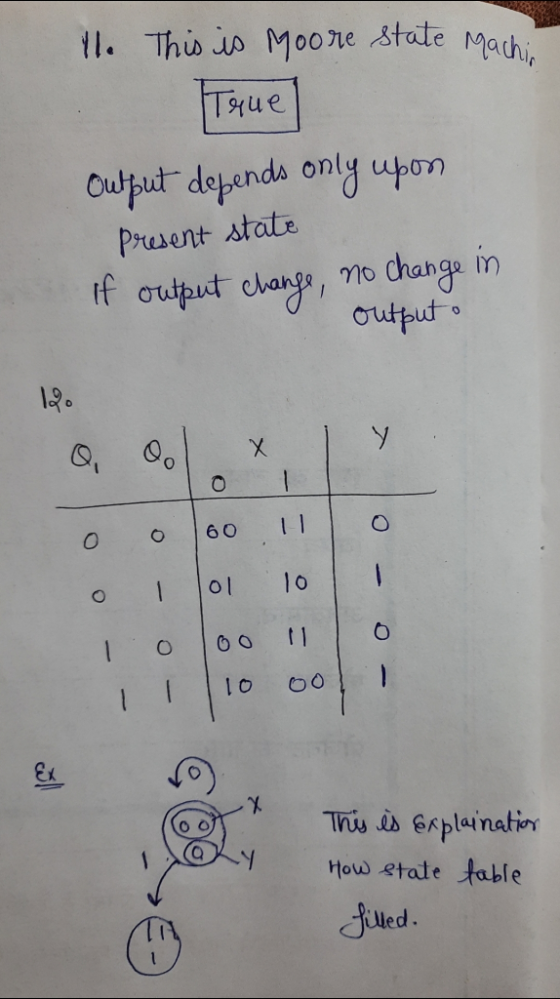
Questions 11-12 are grouped together and share information. 11. (T/F) The state diagram is an example...
show work plz Consider the following finite state diagram. State 1 Output=1 State 0 Output=0 State...
 show work plz
Consider the following finite state diagram. State 1 Output=1 State 0 Output=0 State 2 Output=1 State 3 Output=0 The diagram has 4 states, 1 external input / (in additional to the CLK input), and 1 output bit Y. State 0 is represented by memory bits Qi Qo=00, State 1 is represented by memory bits Q.Qo=01, State 2 is represented by memory bits Q.Qo = 10, and State 3 is represented by memory bits Q.Qo = 11. The...
show work plz
Consider the following finite state diagram. State 1 Output=1 State 0 Output=0 State 2 Output=1 State 3 Output=0 The diagram has 4 states, 1 external input / (in additional to the CLK input), and 1 output bit Y. State 0 is represented by memory bits Qi Qo=00, State 1 is represented by memory bits Q.Qo=01, State 2 is represented by memory bits Q.Qo = 10, and State 3 is represented by memory bits Q.Qo = 11. The...
I need some help with these questions. Draw the minimal state diagram for a single input...
 I need some help with these questions.
Draw the minimal state diagram for a single input sequence detector whose output wil produce a 1 whenever the input sequence 1010 or 1101 is detected. Overlapping input sequences are allowed. 1 2. Write the minimal state table for this sequence detector, begin with state A for the initial state 3. Write the transition table for this sequence detector. Use the state variables starting with w.... Assign state 0 to A, 1 to...
I need some help with these questions.
Draw the minimal state diagram for a single input sequence detector whose output wil produce a 1 whenever the input sequence 1010 or 1101 is detected. Overlapping input sequences are allowed. 1 2. Write the minimal state table for this sequence detector, begin with state A for the initial state 3. Write the transition table for this sequence detector. Use the state variables starting with w.... Assign state 0 to A, 1 to...
1. Given the state diagram shown below for a state machine with one-bit input W and two-bit outpu...
 1. Given the state diagram shown below for a state machine with
one-bit input W and two-bit output Z:
a. (20 points) Using the state assignments below, make the
state-assigned table. Let S0 = 001, S1 = 010, and S2 = 100.
b. (20 points) Let the state variables be Y2, Y1, and Y0. Derive
an expression for each of the next state variables.
c. (10 points) Derive expressions for the output of this state
diagram.
d. (20 points) Draw...
1. Given the state diagram shown below for a state machine with
one-bit input W and two-bit output Z:
a. (20 points) Using the state assignments below, make the
state-assigned table. Let S0 = 001, S1 = 010, and S2 = 100.
b. (20 points) Let the state variables be Y2, Y1, and Y0. Derive
an expression for each of the next state variables.
c. (10 points) Derive expressions for the output of this state
diagram.
d. (20 points) Draw...
8. Suppose that SA, B., F} is a set of states and T 0,1 are the input and output alphabets for th...
 8. Suppose that SA, B., F} is a set of states and T 0,1 are the input and output alphabets for the Mealy machine described by the transition table below. (a) Construct a state diagram for this Mealy machine (Layout the states so that there is no need to have transition arrows crossing each other.) TransitionOutput 0 1 01 b) Find the output string corresponding to the input string 0110010100101', when starting in state A In which state does the...
T1 D Q T2 T Q Clk Figure 1 Sequential Circuit. EXERCISE 2 Consider the circuit...
 T1 D Q T2 T Q Clk Figure 1 Sequential Circuit. EXERCISE 2 Consider the circuit of Figure 1. 1) Is this a Moore or a mealy Machine? Explain briefly. 2) Complete the following transition table for the machine. Use symbols Q2, Qi, and Qo for the JK, T and D flipflops respectively. Next State O2'Q1 Qo Output (Z) Present State x=1 001 010 011 100 101 110 3) Starting at State So, give the shortest sequence taken by X...
5) Decoders: Given the following circuit, S0 and S1 are computed using a 4-2 priority encoder with the priorities indicated on the figure. (hint: IDLE signal is always 0, if any of the inputs...
 5) Decoders: Given the following circuit, S0 and S1 are computed using a 4-2 priority encoder with the priorities indicated on the figure. (hint: IDLE signal is always 0, if any of the inputs 10,11,12, or 13 is 1) 6 points) 4-to-2 Priority Encoder 10 YO YI 13 IDLE 13> 11 > 12>10 12 Full c Adder So Fill the following table showing the output signals S0 and SI given the input signals w, x, y, a) and z. Prof...
8. Suppose that S = {A,B,...,F} is a set of states and I = O = {0,1} are the input and output alp...
 8. Suppose that S = {A,B,...,F} is a set of states and I = O =
{0,1} are the input and output alphabets for the Mealy machine
described by the transition table below.
8. Suppose that S-A, B... . F} is a set of states and I- O- 10, 1} are the input and output alphabets for the Mealy machine described by the transition table below a) Construct a state diagram for this Mealy machine. (Layout the states so that...
8. Suppose that S = {A,B,...,F} is a set of states and I = O =
{0,1} are the input and output alphabets for the Mealy machine
described by the transition table below.
8. Suppose that S-A, B... . F} is a set of states and I- O- 10, 1} are the input and output alphabets for the Mealy machine described by the transition table below a) Construct a state diagram for this Mealy machine. (Layout the states so that...
3. Moore State Machine Design [25 points A sequential circuit has two inputs (X1, X2) and...
 3. Moore State Machine Design [25 points A sequential circuit has two inputs (X1, X2) and one output (Z). The output remains a constant value unless one of the following input sequences occurs: The input sequence X1, X2 01, 1 causes the output to become 0. The input sequence X, X2 10, 11 causes the output to become 1 The input sequence X1, X2 10, 01 causes the output to change value. Provide a state transition table and state graph...
nS[1] nS[O S[O] O Write two Boolean expressions which correspond to the next state logic for...
 nS[1] nS[O S[O] O Write two Boolean expressions which correspond to the next state logic for the machine. That is, express the next state (nS [1] and ns[]) as functions of the present state (S(1:0]) and input (A). 2 Write the Boolean expressions which correspond to the output logic for the machine. That is, express X and Y as functions of the present state and the input (S(1:0) and A). For each of the outputs, identify if they are Mealy...
1. Given the state diagram shown below for a two-state synchronous sequential Mealy circuit with input....
 1. Given the state diagram shown below for a two-state synchronous sequential Mealy circuit with input. and output z, realize the circuit using D flip-flops. Your answer must include the state transition,excita- tion, and output tables, the excitation equation(s), and a labeled circuit diagram 1/0 2. Given the state diagram in Problem 1, realize the circuit using JK flip-flops. Your answer must include the state transition, excitation, and output tables, the excitation equation(s), and a labeled circuit diagram. 3. Given...
 show work plz
Consider the following finite state diagram. State 1 Output=1 State 0 Output=0 State 2 Output=1 State 3 Output=0 The diagram has 4 states, 1 external input / (in additional to the CLK input), and 1 output bit Y. State 0 is represented by memory bits Qi Qo=00, State 1 is represented by memory bits Q.Qo=01, State 2 is represented by memory bits Q.Qo = 10, and State 3 is represented by memory bits Q.Qo = 11. The...
show work plz
Consider the following finite state diagram. State 1 Output=1 State 0 Output=0 State 2 Output=1 State 3 Output=0 The diagram has 4 states, 1 external input / (in additional to the CLK input), and 1 output bit Y. State 0 is represented by memory bits Qi Qo=00, State 1 is represented by memory bits Q.Qo=01, State 2 is represented by memory bits Q.Qo = 10, and State 3 is represented by memory bits Q.Qo = 11. The...
 I need some help with these questions.
Draw the minimal state diagram for a single input sequence detector whose output wil produce a 1 whenever the input sequence 1010 or 1101 is detected. Overlapping input sequences are allowed. 1 2. Write the minimal state table for this sequence detector, begin with state A for the initial state 3. Write the transition table for this sequence detector. Use the state variables starting with w.... Assign state 0 to A, 1 to...
I need some help with these questions.
Draw the minimal state diagram for a single input sequence detector whose output wil produce a 1 whenever the input sequence 1010 or 1101 is detected. Overlapping input sequences are allowed. 1 2. Write the minimal state table for this sequence detector, begin with state A for the initial state 3. Write the transition table for this sequence detector. Use the state variables starting with w.... Assign state 0 to A, 1 to...
 1. Given the state diagram shown below for a state machine with
one-bit input W and two-bit output Z:
a. (20 points) Using the state assignments below, make the
state-assigned table. Let S0 = 001, S1 = 010, and S2 = 100.
b. (20 points) Let the state variables be Y2, Y1, and Y0. Derive
an expression for each of the next state variables.
c. (10 points) Derive expressions for the output of this state
diagram.
d. (20 points) Draw...
1. Given the state diagram shown below for a state machine with
one-bit input W and two-bit output Z:
a. (20 points) Using the state assignments below, make the
state-assigned table. Let S0 = 001, S1 = 010, and S2 = 100.
b. (20 points) Let the state variables be Y2, Y1, and Y0. Derive
an expression for each of the next state variables.
c. (10 points) Derive expressions for the output of this state
diagram.
d. (20 points) Draw...
 8. Suppose that SA, B., F} is a set of states and T 0,1 are the input and output alphabets for the Mealy machine described by the transition table below. (a) Construct a state diagram for this Mealy machine (Layout the states so that there is no need to have transition arrows crossing each other.) TransitionOutput 0 1 01 b) Find the output string corresponding to the input string 0110010100101', when starting in state A In which state does the...
 T1 D Q T2 T Q Clk Figure 1 Sequential Circuit. EXERCISE 2 Consider the circuit of Figure 1. 1) Is this a Moore or a mealy Machine? Explain briefly. 2) Complete the following transition table for the machine. Use symbols Q2, Qi, and Qo for the JK, T and D flipflops respectively. Next State O2'Q1 Qo Output (Z) Present State x=1 001 010 011 100 101 110 3) Starting at State So, give the shortest sequence taken by X...
 5) Decoders: Given the following circuit, S0 and S1 are computed using a 4-2 priority encoder with the priorities indicated on the figure. (hint: IDLE signal is always 0, if any of the inputs 10,11,12, or 13 is 1) 6 points) 4-to-2 Priority Encoder 10 YO YI 13 IDLE 13> 11 > 12>10 12 Full c Adder So Fill the following table showing the output signals S0 and SI given the input signals w, x, y, a) and z. Prof...
 8. Suppose that S = {A,B,...,F} is a set of states and I = O =
{0,1} are the input and output alphabets for the Mealy machine
described by the transition table below.
8. Suppose that S-A, B... . F} is a set of states and I- O- 10, 1} are the input and output alphabets for the Mealy machine described by the transition table below a) Construct a state diagram for this Mealy machine. (Layout the states so that...
8. Suppose that S = {A,B,...,F} is a set of states and I = O =
{0,1} are the input and output alphabets for the Mealy machine
described by the transition table below.
8. Suppose that S-A, B... . F} is a set of states and I- O- 10, 1} are the input and output alphabets for the Mealy machine described by the transition table below a) Construct a state diagram for this Mealy machine. (Layout the states so that...
 3. Moore State Machine Design [25 points A sequential circuit has two inputs (X1, X2) and one output (Z). The output remains a constant value unless one of the following input sequences occurs: The input sequence X1, X2 01, 1 causes the output to become 0. The input sequence X, X2 10, 11 causes the output to become 1 The input sequence X1, X2 10, 01 causes the output to change value. Provide a state transition table and state graph...
 nS[1] nS[O S[O] O Write two Boolean expressions which correspond to the next state logic for the machine. That is, express the next state (nS [1] and ns[]) as functions of the present state (S(1:0]) and input (A). 2 Write the Boolean expressions which correspond to the output logic for the machine. That is, express X and Y as functions of the present state and the input (S(1:0) and A). For each of the outputs, identify if they are Mealy...
 1. Given the state diagram shown below for a two-state synchronous sequential Mealy circuit with input. and output z, realize the circuit using D flip-flops. Your answer must include the state transition,excita- tion, and output tables, the excitation equation(s), and a labeled circuit diagram 1/0 2. Given the state diagram in Problem 1, realize the circuit using JK flip-flops. Your answer must include the state transition, excitation, and output tables, the excitation equation(s), and a labeled circuit diagram. 3. Given...
Most questions answered within 3 hours.
-
Where is the error in this code sequence?
String s1 = "Hello";
String s2 = "ello";...
asked 10 months ago -
Financial data for Joel de Paris, Inc., for last year
follow:
Joel de Paris, Inc.
Balance...
asked 10 months ago -
Consider this reaction:
Al2(SO4)3 (aq)+ BaCl3
(aq) Al2Cl6 (aq)- +
3BaSO4(s) . What is the...
asked 10 months ago -
Suppose that Savneet is considering increasing her
recent random sample from 20 car rentals to 40...
asked 10 months ago -
Trucks arrive at an unloading terminal at an average rate of 120
per hour.
Trucks arrive...
asked 10 months ago -
Why are methanol and ethanol completely soluble in water while
octanol is not very little soluble....
asked 10 months ago -
A facilities manager at a university reads in a research report
that the mean amount of...
asked 10 months ago -
When the CuSO4 is rehydrated by adding water to the anhydrous
compound, is this an endothermic...
asked 10 months ago -
A ray of sunlight is passing from diamond into crown glass; the
angle of incidence is...
asked 10 months ago -
A block of mass 0.249 kg is placed on top of a light, vertical
spring of...
asked 10 months ago -
how do the kidneys compensate in the presences of acidosis
a) trigger hyperventilate
b) reserve acid...
asked 10 months ago -
Question 501 pts
The rental rate of capital to the firm increases. Which of the
following...
asked 10 months ago