
Homework Answers
Add Answer to:
The figure shows the free-body diagram of a connecting-link portion made of AISI 1020 having stress...
The figure shows the free-body diagram of a connecting-link portion having stress concentration at three sections....
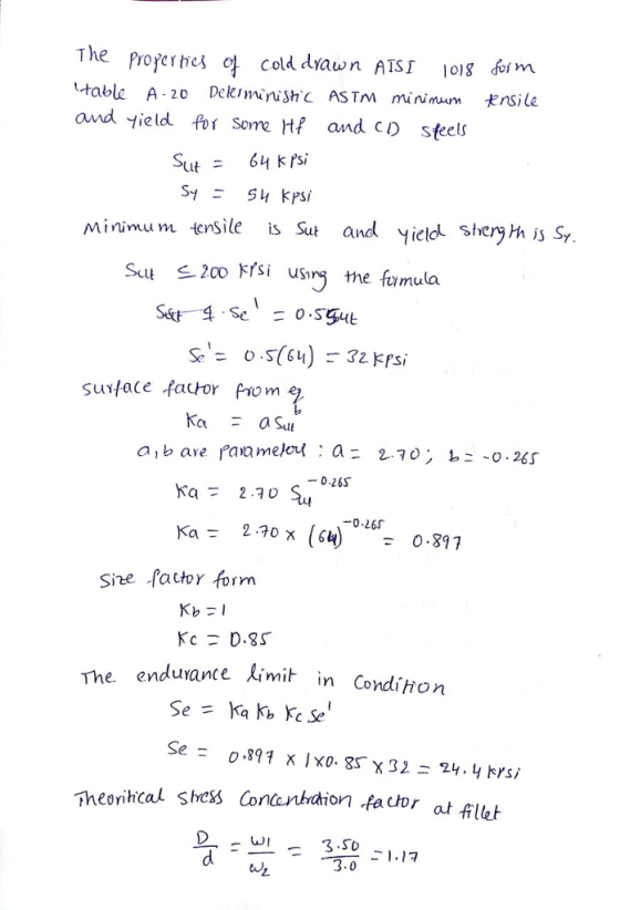
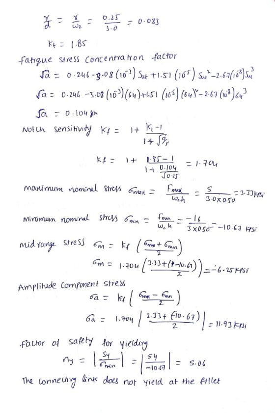
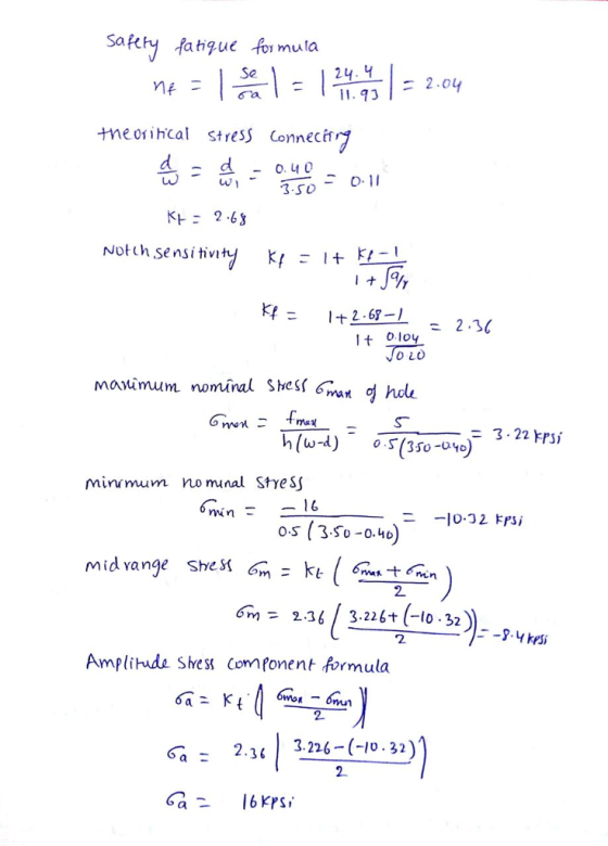
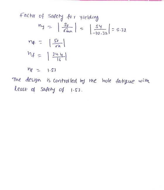
 The figure shows the free-body diagram of a connecting-link portion having stress concentration at three sections. The dimensions are 0.25 in, d 0.40 in, h= 0.50 in, wl = 3.50 in, and w2= 3.0 in. The forces F fluctuate between a tension of 15 kip and a compression of 46 kip. Neglect column action and find the least factor of safety if the material is cold-drawn AISI 1018 steel. А Section -
Question 2 The figure shows the free-body diagram of a connecting-link portion having stress concentration at...
 Question 2 The figure shows the free-body diagram of a connecting-link portion having stress concentration at three sections. The dimensions are r=0.25 in. d=0.40 in, h = 0.50 in, wl= 3.50 in, and w2 = 3.0 in. The forces F fluctuate between a tension of 15 kip and a compression of 46 kip. Neglect column action and find the least factor of safety if the material is cold-drawn AISI 1018 steel T- Section A-A I
An shown in the folloing figure, shaft A. made of AISI 1020 hot-rolled steelis welded to...
 An shown in the folloing figure, shaft A. made of AISI 1020 hot-rolled steelis welded to a ised suppot and is subjected to loading by simultaneous forces Fr and F:via shat B. A theoretieal stress concentration factor K of 1.6 and K, of 1.4 is induced in the shat by the E in weld fillet 1 he, lengi h of shaft A from the fixed support to the connection at shaft B is 2 ft. The load cycles thom 1S0...
The cantilever bar in the figure is made from AISI 1018 CD steel and is statically loaded
 The cantilever bar in the figure is made from AISI 1018 CD
steel and is statically loaded with Fy = 800 N, and Fx = Fz = 0.
The fillet radius at the wall is 2 mm with theoretical stress
concentrations of 1.5 for bending, 1.2 for axial, and 2.1 for
torsion.Sut = 440 MPa = 64 kpsi, Sy = 370 MPa = 54 kpsi. Analyze the
stress situation in rod AB by obtaining the following
information.a) Determine the precise...
The cantilever bar in the figure is made from AISI 1018 CD
steel and is statically loaded with Fy = 800 N, and Fx = Fz = 0.
The fillet radius at the wall is 2 mm with theoretical stress
concentrations of 1.5 for bending, 1.2 for axial, and 2.1 for
torsion.Sut = 440 MPa = 64 kpsi, Sy = 370 MPa = 54 kpsi. Analyze the
stress situation in rod AB by obtaining the following
information.a) Determine the precise...
 The figure shows the free-body diagram of a connecting-link portion having stress concentration at three sections. The dimensions are 0.25 in, d 0.40 in, h= 0.50 in, wl = 3.50 in, and w2= 3.0 in. The forces F fluctuate between a tension of 15 kip and a compression of 46 kip. Neglect column action and find the least factor of safety if the material is cold-drawn AISI 1018 steel. А Section -
 Question 2 The figure shows the free-body diagram of a connecting-link portion having stress concentration at three sections. The dimensions are r=0.25 in. d=0.40 in, h = 0.50 in, wl= 3.50 in, and w2 = 3.0 in. The forces F fluctuate between a tension of 15 kip and a compression of 46 kip. Neglect column action and find the least factor of safety if the material is cold-drawn AISI 1018 steel T- Section A-A I
 An shown in the folloing figure, shaft A. made of AISI 1020 hot-rolled steelis welded to a ised suppot and is subjected to loading by simultaneous forces Fr and F:via shat B. A theoretieal stress concentration factor K of 1.6 and K, of 1.4 is induced in the shat by the E in weld fillet 1 he, lengi h of shaft A from the fixed support to the connection at shaft B is 2 ft. The load cycles thom 1S0...
 The cantilever bar in the figure is made from AISI 1018 CD
steel and is statically loaded with Fy = 800 N, and Fx = Fz = 0.
The fillet radius at the wall is 2 mm with theoretical stress
concentrations of 1.5 for bending, 1.2 for axial, and 2.1 for
torsion.Sut = 440 MPa = 64 kpsi, Sy = 370 MPa = 54 kpsi. Analyze the
stress situation in rod AB by obtaining the following
information.a) Determine the precise...
The cantilever bar in the figure is made from AISI 1018 CD
steel and is statically loaded with Fy = 800 N, and Fx = Fz = 0.
The fillet radius at the wall is 2 mm with theoretical stress
concentrations of 1.5 for bending, 1.2 for axial, and 2.1 for
torsion.Sut = 440 MPa = 64 kpsi, Sy = 370 MPa = 54 kpsi. Analyze the
stress situation in rod AB by obtaining the following
information.a) Determine the precise...
Most questions answered within 3 hours.
-
Where is the error in this code sequence?
String s1 = "Hello";
String s2 = "ello";...
asked 11 months ago -
Financial data for Joel de Paris, Inc., for last year
follow:
Joel de Paris, Inc.
Balance...
asked 11 months ago -
Consider this reaction:
Al2(SO4)3 (aq)+ BaCl3
(aq) Al2Cl6 (aq)- +
3BaSO4(s) . What is the...
asked 11 months ago -
Suppose that Savneet is considering increasing her
recent random sample from 20 car rentals to 40...
asked 11 months ago -
Trucks arrive at an unloading terminal at an average rate of 120
per hour.
Trucks arrive...
asked 11 months ago -
Why are methanol and ethanol completely soluble in water while
octanol is not very little soluble....
asked 11 months ago -
A facilities manager at a university reads in a research report
that the mean amount of...
asked 11 months ago -
When the CuSO4 is rehydrated by adding water to the anhydrous
compound, is this an endothermic...
asked 11 months ago -
A ray of sunlight is passing from diamond into crown glass; the
angle of incidence is...
asked 11 months ago -
A block of mass 0.249 kg is placed on top of a light, vertical
spring of...
asked 11 months ago -
how do the kidneys compensate in the presences of acidosis
a) trigger hyperventilate
b) reserve acid...
asked 11 months ago -
Question 501 pts
The rental rate of capital to the firm increases. Which of the
following...
asked 11 months ago