

Homework Answers

Add Answer to:
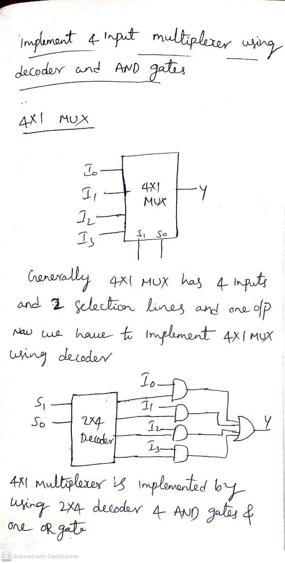
Problem 1. Sequential Circuit Design Using a decoder and AND gates, implement a 4-input multiplexer. ....
Task 1: One implementation of a multiplexer uses a decoder. Using Logic Circuit,create a new schematic,...
 Task 1: One implementation of a multiplexer uses a decoder. Using Logic Circuit,create a new schematic, import one of the decoders created in a previous lab and create a logic dircuit that implements the truth table below Task 2: Create a logic circuit that can display two 4-bit digits on two 7-segment displays using a single 7- segment display decoder and 4 multiplexers. To do this you will use four switches to enter the first number, and a second set...
Design 3- to – 8 decoder using logic gates with enabler, AND, NOT, etc..? Design 3- to – 8 decode...
Design 3- to – 8 decoder using logic gates with enabler, AND, NOT, etc..? Design 3- to – 8 decoder using only two 2-to-4 decoders graphical blocks, use enabler input? a) Design a 3-bit ripple-carry adder using AND, OR, NOT, EXOR, etc.; include carry-in (Cin), carry-out (Cout) and overflow input/output signals? Note: Design for 1-bit first, then extrapolate to 4-bit using 1-bit full-adder graphical block. Design a 3-bit ripple-carry subtractor using AND, OR, NOT, EXOR, etc..; include carry-in (Cin), carry-out...
Implement the function f (A,B,C,D) summation(m(0,2,5,8,12,13,14,15)) using: a. A 4-to-1 multiplexer, and external gates. Choose inputs...
Implement the function f (A,B,C,D) summation(m(0,2,5,8,12,13,14,15)) using: a. A 4-to-1 multiplexer, and external gates. Choose inputs A and B as the select lines. b. A 4-to-16 decoder and OR gate c. A PLA
Multiplexer Example Implement the following Boolean function using a 4x1 Mux;
 Multiplexer Example Implement the following Boolean function using a 4x1 Mux; F(x,y,z) = Σ (1,2,6,7) Decoder Example Implement the following functions for a full adder using decoder; S(x,y,z) = Σ (1,2,4,7) C(x,y,z) = Σ (3,5,6,7) Implement the following Boolean function; F(x,y,z) = Σ (0,2,3,7): Using; 1. Two 2x4 decoders and logic gates 2. One 4x1 multiplexer Decoder . Draw the truth table for the function to be implemented. . Pick the terms for output. . Derive appropriate logic to combine terms. . Use two 2x4 decoders to make one3x8 decoder. . Pay attention to fact...
Implement Full adder using 8 times 1 multiplexer. Implement Full adder using 4 times 1 multiplexer....
 Implement Full adder using 8 times 1 multiplexer. Implement Full adder using 4 times 1 multiplexer. Show the Implementation adding two (4-bit numbers) using full adders. What is the main difference between pulse-trigger, positive-edge trigger and negative-edge trigger D Flip-flop? Design and implement a sequential circuit that can detect the code "111"with repetition. Show the state diagram, stale table and the circuit.
3. [20 pts] 8-segment decoder for 8 symbols. Implement (draw logic diagram) the segment 4 of the 8-segment decoder...
 3. [20 pts] 8-segment decoder for 8 symbols. Implement (draw logic diagram) the segment 4 of the 8-segment decoder for 8 symbols 0 (a) Using K-map to realize the function q 16 pts) (b) Using a 3-8 decoder and OR gates to realize the function q.[7 pts] (e Using 8-to-1 multiplexer to realize the function 17 pts] Notes: 1. A eight-segment decoder is a combinational circuit with a three-bit input a and a 8-bit output q. Each bit of q...
Problem 3 [10 points a) (5 points) Construct a circuit that takes as input a 3-bit number X-XXXo ...
 part c
Problem 3 [10 points a) (5 points) Construct a circuit that takes as input a 3-bit number X-XXXo and increments it by one. L.e. if the input is 101 the output should be 110. Use only half adders. b) Construct a circuit that takes as input a 3-bit number X-XXxo and decrements it by one 1. (5 points) Show the truth table of the circuit. Then use a decoder and additional gates to implement it. So Ys Y2...
part c
Problem 3 [10 points a) (5 points) Construct a circuit that takes as input a 3-bit number X-XXXo and increments it by one. L.e. if the input is 101 the output should be 110. Use only half adders. b) Construct a circuit that takes as input a 3-bit number X-XXxo and decrements it by one 1. (5 points) Show the truth table of the circuit. Then use a decoder and additional gates to implement it. So Ys Y2...
computer architecture 4. Design a 2-to-4-line decoder with enable using inverters 2to-4-line decoder vi AND gates...
 computer architecture
4. Design a 2-to-4-line decoder with enable using inverters 2to-4-line decoder vi AND gates and
computer architecture
4. Design a 2-to-4-line decoder with enable using inverters 2to-4-line decoder vi AND gates and
Design a combinational circuit that accepts a 2-bit number and generates a 4-bit binary number output...
 Design a combinational circuit that accepts a 2-bit number and generates a 4-bit binary number output equal to the square of the input number. Use Decoder and any other external gates as necessary to implement your design. Draw the logic diagram and clearly label all input and output lines.
1. Using only half adders, design a four-bit incrementer circuit (a circuit that adds 1 to...
 1. Using only half adders, design a four-bit incrementer circuit (a circuit that adds 1 to a four- bit binary number). 2. Using only 2-to-4 line decoders with enable, construct a 4-to-16 line decoder. 3. Using a decoder and external gates, design the combinational circuit defined by the following three Boolean functions: F = x'y'z' + x2 F2 = xy'z' + x'y F3 = x'y'z + xy
 Task 1: One implementation of a multiplexer uses a decoder. Using Logic Circuit,create a new schematic, import one of the decoders created in a previous lab and create a logic dircuit that implements the truth table below Task 2: Create a logic circuit that can display two 4-bit digits on two 7-segment displays using a single 7- segment display decoder and 4 multiplexers. To do this you will use four switches to enter the first number, and a second set...
 Implement Full adder using 8 times 1 multiplexer. Implement Full adder using 4 times 1 multiplexer. Show the Implementation adding two (4-bit numbers) using full adders. What is the main difference between pulse-trigger, positive-edge trigger and negative-edge trigger D Flip-flop? Design and implement a sequential circuit that can detect the code "111"with repetition. Show the state diagram, stale table and the circuit.
 3. [20 pts] 8-segment decoder for 8 symbols. Implement (draw logic diagram) the segment 4 of the 8-segment decoder for 8 symbols 0 (a) Using K-map to realize the function q 16 pts) (b) Using a 3-8 decoder and OR gates to realize the function q.[7 pts] (e Using 8-to-1 multiplexer to realize the function 17 pts] Notes: 1. A eight-segment decoder is a combinational circuit with a three-bit input a and a 8-bit output q. Each bit of q...
 part c
Problem 3 [10 points a) (5 points) Construct a circuit that takes as input a 3-bit number X-XXXo and increments it by one. L.e. if the input is 101 the output should be 110. Use only half adders. b) Construct a circuit that takes as input a 3-bit number X-XXxo and decrements it by one 1. (5 points) Show the truth table of the circuit. Then use a decoder and additional gates to implement it. So Ys Y2...
part c
Problem 3 [10 points a) (5 points) Construct a circuit that takes as input a 3-bit number X-XXXo and increments it by one. L.e. if the input is 101 the output should be 110. Use only half adders. b) Construct a circuit that takes as input a 3-bit number X-XXxo and decrements it by one 1. (5 points) Show the truth table of the circuit. Then use a decoder and additional gates to implement it. So Ys Y2...
 computer architecture
4. Design a 2-to-4-line decoder with enable using inverters 2to-4-line decoder vi AND gates and
computer architecture
4. Design a 2-to-4-line decoder with enable using inverters 2to-4-line decoder vi AND gates and
 Design a combinational circuit that accepts a 2-bit number and generates a 4-bit binary number output equal to the square of the input number. Use Decoder and any other external gates as necessary to implement your design. Draw the logic diagram and clearly label all input and output lines.
 1. Using only half adders, design a four-bit incrementer circuit (a circuit that adds 1 to a four- bit binary number). 2. Using only 2-to-4 line decoders with enable, construct a 4-to-16 line decoder. 3. Using a decoder and external gates, design the combinational circuit defined by the following three Boolean functions: F = x'y'z' + x2 F2 = xy'z' + x'y F3 = x'y'z + xy
Most questions answered within 3 hours.
-
Where is the error in this code sequence?
String s1 = "Hello";
String s2 = "ello";...
asked 11 months ago -
Financial data for Joel de Paris, Inc., for last year
follow:
Joel de Paris, Inc.
Balance...
asked 11 months ago -
Consider this reaction:
Al2(SO4)3 (aq)+ BaCl3
(aq) Al2Cl6 (aq)- +
3BaSO4(s) . What is the...
asked 11 months ago -
Suppose that Savneet is considering increasing her
recent random sample from 20 car rentals to 40...
asked 11 months ago -
Trucks arrive at an unloading terminal at an average rate of 120
per hour.
Trucks arrive...
asked 11 months ago -
Why are methanol and ethanol completely soluble in water while
octanol is not very little soluble....
asked 11 months ago -
A facilities manager at a university reads in a research report
that the mean amount of...
asked 11 months ago -
When the CuSO4 is rehydrated by adding water to the anhydrous
compound, is this an endothermic...
asked 11 months ago -
A ray of sunlight is passing from diamond into crown glass; the
angle of incidence is...
asked 11 months ago -
A block of mass 0.249 kg is placed on top of a light, vertical
spring of...
asked 11 months ago -
how do the kidneys compensate in the presences of acidosis
a) trigger hyperventilate
b) reserve acid...
asked 11 months ago -
Question 501 pts
The rental rate of capital to the firm increases. Which of the
following...
asked 11 months ago