
Homework Answers


Add Answer to:
be Acrobat Reader DC Araclar QUIZ-3.pdf QUESTION-2 A wood beam supports the loads shown in Figure...
A wood beam supports the loads shown. The cross-sectional dimensions of the beam are shown in...
 A wood beam supports the loads shown. The cross-sectional dimensions of the beam are shown in the second figure. Assume LAB=2.8 m, LBC=1.1 m, LCD=1.6 m, w=12 kN/m, P=6.8 kN, b1=20 mm, b2=75 mm, d1=100 mm, and dz=240 mm. Determine the magnitude of: (a) the maximum horizontal shear stress Tmax in the beam. (b) the maximum tension bending stress max (and location x) in the beam. - X BI ec LAB I LBCI LCDJ bil b2 bil Answers: kPa. (a)...
A cantilever beam supports the loads shown. The cross-sectional dimensions of the shape are also shown....
 A cantilever beam supports the
loads shown. The cross-sectional dimensions of the shape are also
shown. Assume LAB = 4.0 ft,
LBC = 12.0 ft, w = 1620 lb/ft,
P = 2550 lb, b = 16 in., d = 6 in.,
t = 0.50 in. Determine
(a) the maximum horizontal shear stress.
(b) the maximum compression bending stress.
(c) the maximum tension bending stress.
Chapter 9, Supplemental Question 043 (GO Tutorial) A cantilever beam supports the loads shown. The cross...
A cantilever beam supports the
loads shown. The cross-sectional dimensions of the shape are also
shown. Assume LAB = 4.0 ft,
LBC = 12.0 ft, w = 1620 lb/ft,
P = 2550 lb, b = 16 in., d = 6 in.,
t = 0.50 in. Determine
(a) the maximum horizontal shear stress.
(b) the maximum compression bending stress.
(c) the maximum tension bending stress.
Chapter 9, Supplemental Question 043 (GO Tutorial) A cantilever beam supports the loads shown. The cross...
A cantilever beam supports the loads shown. The cross-sectional dimensions of the shape are also shown....
 A cantilever beam supports the loads shown. The cross-sectional
dimensions of the shape are also shown. Assume
LAB = 3.5 ft, LBC = 10.5
ft, w = 1380 lb/ft, P = 2600 lb, b = 15
in., d = 7 in., t = 0.35 in. Determine
(a) the maximum horizontal shear stress.
(b) the maximum compression bending stress.
(c) the maximum tension bending stress.
2 LAB LBC Answers
A cantilever beam supports the loads shown. The cross-sectional
dimensions of the shape are also shown. Assume
LAB = 3.5 ft, LBC = 10.5
ft, w = 1380 lb/ft, P = 2600 lb, b = 15
in., d = 7 in., t = 0.35 in. Determine
(a) the maximum horizontal shear stress.
(b) the maximum compression bending stress.
(c) the maximum tension bending stress.
2 LAB LBC Answers
A cantilever beam supports the loads shown. The cross-sectional dimensions of the shape are also shown....
 A cantilever beam supports the loads shown. The cross-sectional dimensions of the shape are also shown. Assume mm, by - 85 mm, 5 mm, 9 mm. Determine - 0.5 m, P. - 4.0 kN, Pg - 7.5 kN, Pe-2.0 kN, -85 (a) the maximum vertical shear stress. (b) the maximum compression bending stress. (c) the maximum tension bending stress. See the coordinate system for the beam in the problem figure with the origin of the x axis at the feed...
P9.037 A cantilever beam supports the loads shown. The cross-sectional dimensions of the shape are also shown. Assume LAB-2.5 ft, LBc 7.5 ft, w 1500 lb/ft, P-2100 lb, b-15 in., d-8 in., t 0.45 in. De...
 P9.037 A cantilever beam supports the loads shown. The cross-sectional dimensions of the shape are also shown. Assume LAB-2.5 ft, LBc 7.5 ft, w 1500 lb/ft, P-2100 lb, b-15 in., d-8 in., t 0.45 in. Determine (a) the maximum horizontal shear stress. (b) the maximum compression bending stress. (c) the maximum tension bending stress BC MB Answers: ksi ƠC,ma,- (b) ksi ƠT,max= (c)
P9.037 A cantilever beam supports the loads shown. The cross-sectional dimensions of the shape are also shown....
P9.037 A cantilever beam supports the loads shown. The cross-sectional dimensions of the shape are also shown. Assume LAB-2.5 ft, LBc 7.5 ft, w 1500 lb/ft, P-2100 lb, b-15 in., d-8 in., t 0.45 in. Determine (a) the maximum horizontal shear stress. (b) the maximum compression bending stress. (c) the maximum tension bending stress BC MB Answers: ksi ƠC,ma,- (b) ksi ƠT,max= (c)
P9.037 A cantilever beam supports the loads shown. The cross-sectional dimensions of the shape are also shown....
A 5-m-long simply supported timber beam carries two concentrated loads as shown dimensions of the beam...
 A 5-m-long simply supported timber beam carries two concentrated loads as shown dimensions of the beam are shown a) At section a-a e the magnitude of the shear stress in the beam at point H. -7748 KNIm in the beam at point K the beam, at any location within the 5-m span length. V occurs in the beam at any location within the 5-m span length.)diagr. the magnitude of the shear stress (b) At section a-a, (e) Determine the maximum...
System Description The system consists of a beam with (see figure 1) Two simple supports A...
 System Description The system consists of a beam with (see figure 1) Two simple supports A distributed load and a concentrated load An inverted "U" shaped cross section (see figure 2); moment of inertia 9 in 200 lbf/in、 650 Ibf 10° 30 21" 40 Figure 1-system to be analyzed L4.5 1.72.25" NA 5.75 3.5 1.75" 1.5 Figure 2-cross section to be used Questions-Given that the applied loads and dimensions do the following 25 points 1. Determine and draw a shear...
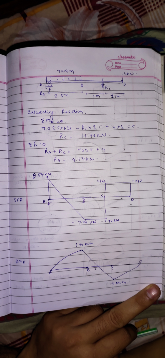
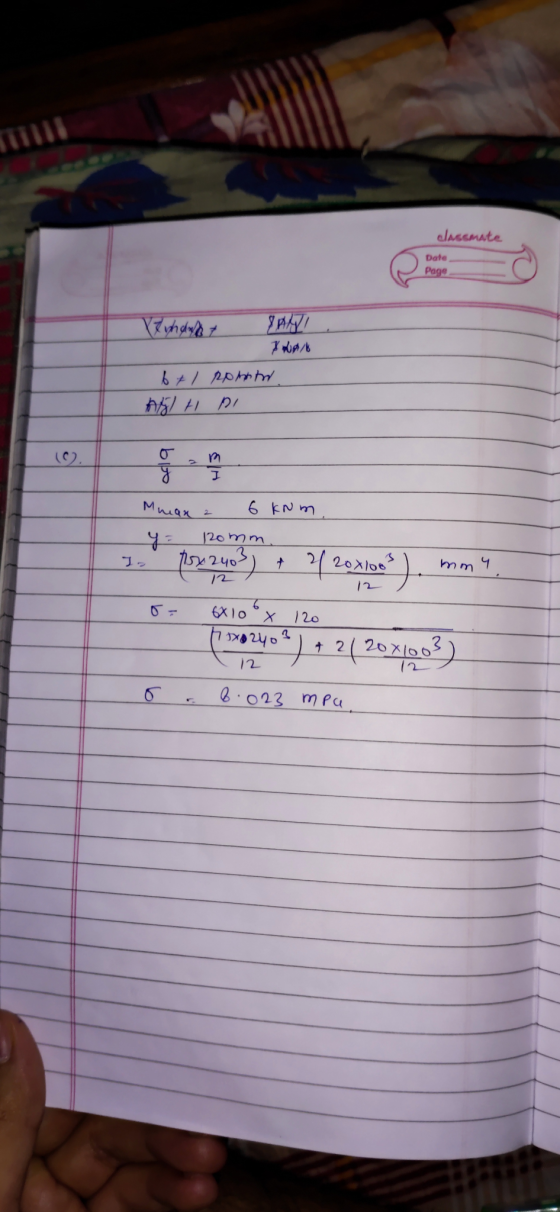
2. A rectangular overhanging beam and loads are shown in the following figure. A. Draw the...
 2. A rectangular overhanging beam and loads are shown in the following figure. A. Draw the shear and bending-moment diagrams B. Determine the maximum absolute value of the shear and absolute maximum bending stress. 16KN/m 45KN (15pts) Sem 4m 2m- 8 cm
A flanged wooden shape is used to support the loads shown on the beam. The dimensions...
 A flanged wooden shape is used to support the loads shown on the beam. The dimensions of the shape are shown in the second figure. Assume LAB = 7 ft, Lec = 4 ft, Lcd = 4 ft, LDE = 2 ft, Pc = 1730 lb, PE = 2320 lb, WAB = 710 lb/ft, b = 8 in., b2 = 2 in., b3 = 5 in., da = 2 in., d2 = 7 in., dz = 2 in. Consider the...
4. A T-shaped cross-sectional beam is loaded as shown in the figure. Determine the following a....
 4. A T-shaped cross-sectional beam is loaded as shown in the figure. Determine the following a. Sketch the internal shear force and bending moment diagrams for the beam. b. Calculate the maximum magnitude of the bending stress. Indicate where this occurs on the cross-section and along the length of the beam. c. Calculate the transverse shearing stress at the centroid of the cross-section using the maximum magnitude of the transverse shear force. - 200 mm 8 KN 1.5 kN/m 20...
 A wood beam supports the loads shown. The cross-sectional dimensions of the beam are shown in the second figure. Assume LAB=2.8 m, LBC=1.1 m, LCD=1.6 m, w=12 kN/m, P=6.8 kN, b1=20 mm, b2=75 mm, d1=100 mm, and dz=240 mm. Determine the magnitude of: (a) the maximum horizontal shear stress Tmax in the beam. (b) the maximum tension bending stress max (and location x) in the beam. - X BI ec LAB I LBCI LCDJ bil b2 bil Answers: kPa. (a)...
 A cantilever beam supports the
loads shown. The cross-sectional dimensions of the shape are also
shown. Assume LAB = 4.0 ft,
LBC = 12.0 ft, w = 1620 lb/ft,
P = 2550 lb, b = 16 in., d = 6 in.,
t = 0.50 in. Determine
(a) the maximum horizontal shear stress.
(b) the maximum compression bending stress.
(c) the maximum tension bending stress.
Chapter 9, Supplemental Question 043 (GO Tutorial) A cantilever beam supports the loads shown. The cross...
A cantilever beam supports the
loads shown. The cross-sectional dimensions of the shape are also
shown. Assume LAB = 4.0 ft,
LBC = 12.0 ft, w = 1620 lb/ft,
P = 2550 lb, b = 16 in., d = 6 in.,
t = 0.50 in. Determine
(a) the maximum horizontal shear stress.
(b) the maximum compression bending stress.
(c) the maximum tension bending stress.
Chapter 9, Supplemental Question 043 (GO Tutorial) A cantilever beam supports the loads shown. The cross...
 A cantilever beam supports the loads shown. The cross-sectional
dimensions of the shape are also shown. Assume
LAB = 3.5 ft, LBC = 10.5
ft, w = 1380 lb/ft, P = 2600 lb, b = 15
in., d = 7 in., t = 0.35 in. Determine
(a) the maximum horizontal shear stress.
(b) the maximum compression bending stress.
(c) the maximum tension bending stress.
2 LAB LBC Answers
A cantilever beam supports the loads shown. The cross-sectional
dimensions of the shape are also shown. Assume
LAB = 3.5 ft, LBC = 10.5
ft, w = 1380 lb/ft, P = 2600 lb, b = 15
in., d = 7 in., t = 0.35 in. Determine
(a) the maximum horizontal shear stress.
(b) the maximum compression bending stress.
(c) the maximum tension bending stress.
2 LAB LBC Answers
 A cantilever beam supports the loads shown. The cross-sectional dimensions of the shape are also shown. Assume mm, by - 85 mm, 5 mm, 9 mm. Determine - 0.5 m, P. - 4.0 kN, Pg - 7.5 kN, Pe-2.0 kN, -85 (a) the maximum vertical shear stress. (b) the maximum compression bending stress. (c) the maximum tension bending stress. See the coordinate system for the beam in the problem figure with the origin of the x axis at the feed...
 P9.037 A cantilever beam supports the loads shown. The cross-sectional dimensions of the shape are also shown. Assume LAB-2.5 ft, LBc 7.5 ft, w 1500 lb/ft, P-2100 lb, b-15 in., d-8 in., t 0.45 in. Determine (a) the maximum horizontal shear stress. (b) the maximum compression bending stress. (c) the maximum tension bending stress BC MB Answers: ksi ƠC,ma,- (b) ksi ƠT,max= (c)
P9.037 A cantilever beam supports the loads shown. The cross-sectional dimensions of the shape are also shown....
P9.037 A cantilever beam supports the loads shown. The cross-sectional dimensions of the shape are also shown. Assume LAB-2.5 ft, LBc 7.5 ft, w 1500 lb/ft, P-2100 lb, b-15 in., d-8 in., t 0.45 in. Determine (a) the maximum horizontal shear stress. (b) the maximum compression bending stress. (c) the maximum tension bending stress BC MB Answers: ksi ƠC,ma,- (b) ksi ƠT,max= (c)
P9.037 A cantilever beam supports the loads shown. The cross-sectional dimensions of the shape are also shown....
 A 5-m-long simply supported timber beam carries two concentrated loads as shown dimensions of the beam are shown a) At section a-a e the magnitude of the shear stress in the beam at point H. -7748 KNIm in the beam at point K the beam, at any location within the 5-m span length. V occurs in the beam at any location within the 5-m span length.)diagr. the magnitude of the shear stress (b) At section a-a, (e) Determine the maximum...
 System Description The system consists of a beam with (see figure 1) Two simple supports A distributed load and a concentrated load An inverted "U" shaped cross section (see figure 2); moment of inertia 9 in 200 lbf/in、 650 Ibf 10° 30 21" 40 Figure 1-system to be analyzed L4.5 1.72.25" NA 5.75 3.5 1.75" 1.5 Figure 2-cross section to be used Questions-Given that the applied loads and dimensions do the following 25 points 1. Determine and draw a shear...
 2. A rectangular overhanging beam and loads are shown in the following figure. A. Draw the shear and bending-moment diagrams B. Determine the maximum absolute value of the shear and absolute maximum bending stress. 16KN/m 45KN (15pts) Sem 4m 2m- 8 cm
 A flanged wooden shape is used to support the loads shown on the beam. The dimensions of the shape are shown in the second figure. Assume LAB = 7 ft, Lec = 4 ft, Lcd = 4 ft, LDE = 2 ft, Pc = 1730 lb, PE = 2320 lb, WAB = 710 lb/ft, b = 8 in., b2 = 2 in., b3 = 5 in., da = 2 in., d2 = 7 in., dz = 2 in. Consider the...
 4. A T-shaped cross-sectional beam is loaded as shown in the figure. Determine the following a. Sketch the internal shear force and bending moment diagrams for the beam. b. Calculate the maximum magnitude of the bending stress. Indicate where this occurs on the cross-section and along the length of the beam. c. Calculate the transverse shearing stress at the centroid of the cross-section using the maximum magnitude of the transverse shear force. - 200 mm 8 KN 1.5 kN/m 20...
Most questions answered within 3 hours.
-
Where is the error in this code sequence?
String s1 = "Hello";
String s2 = "ello";...
asked 10 months ago -
Financial data for Joel de Paris, Inc., for last year
follow:
Joel de Paris, Inc.
Balance...
asked 10 months ago -
Consider this reaction:
Al2(SO4)3 (aq)+ BaCl3
(aq) Al2Cl6 (aq)- +
3BaSO4(s) . What is the...
asked 10 months ago -
Suppose that Savneet is considering increasing her
recent random sample from 20 car rentals to 40...
asked 10 months ago -
Trucks arrive at an unloading terminal at an average rate of 120
per hour.
Trucks arrive...
asked 10 months ago -
Why are methanol and ethanol completely soluble in water while
octanol is not very little soluble....
asked 10 months ago -
A facilities manager at a university reads in a research report
that the mean amount of...
asked 10 months ago -
When the CuSO4 is rehydrated by adding water to the anhydrous
compound, is this an endothermic...
asked 10 months ago -
A ray of sunlight is passing from diamond into crown glass; the
angle of incidence is...
asked 10 months ago -
A block of mass 0.249 kg is placed on top of a light, vertical
spring of...
asked 10 months ago -
how do the kidneys compensate in the presences of acidosis
a) trigger hyperventilate
b) reserve acid...
asked 10 months ago -
Question 501 pts
The rental rate of capital to the firm increases. Which of the
following...
asked 10 months ago