the following problem is of a two-mass system. I have 2 questions
1. find the transfer function from input F2 to output x1
2. for the transfer function found, determine the sensitivity to variation in parameter B12
note: i already found the differential eqns of motion for t>0

Homework Answers
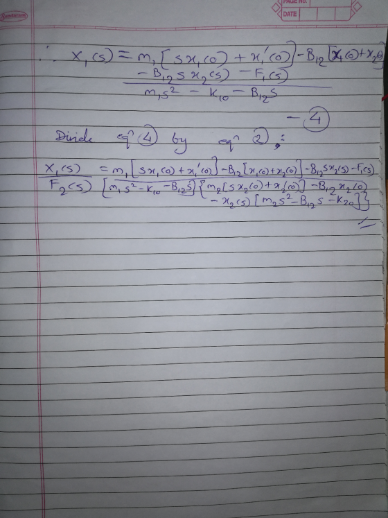
Firstly, find the differential equations by applying laws of
dynamic equilibrium. Subsequently, take the laplace transforms and
express the equations in terms of X1(s) and F2(s). And finally,
divide X1(s) by F2(s).
Add Answer to:
the following problem is of a two-mass system. I have 2
questions
1. find the transfer...
Problem B-4-1 Find the transfer function X (s)/X/(s) of the mechanical system shown in Figure 4-50....
 Problem B-4-1 Find the transfer function X (s)/X/(s) of the mechanical system shown in Figure 4-50. The displacements x; and X, are measured from their respective equilibrium positions. Obtain the displacement xo(t) when the input x;(t) is a step displacement of magnitude X; occurring at t = 0. Assume that x.(0-) = 0. T Figure 4-50 Mechanical system.
For the system shown in Fig. 1, solve the following problems. (a) Find the transfer function, G(s...
 For the system shown in Fig. 1, solve the following problems. (a) Find the transfer function, G(s)X2 (s)/F(s) (b) Does the system oscillate with a unit step input (f (t))? Explain the reason (c) Decide if the system(x2 (t)) is stable with a unit step input (f (t))? Explain the reason 1. 320) 8 kg 2 N/m 4N-s/m 2N-s/m Fig. 1 2. There are two suspensions for a car as shown in Fig. 2 (a) Find the equations of each...
Doing a system dynamics problem I have found a transfer function to be 1/(2s+4). Can you...
Doing a system dynamics problem I have found a transfer function to be 1/(2s+4). Can you show me how to get the transient, steady state as well as the homogenous, particular solutions? Each pair added should be equivalent but my answers are not agreeing. By taking inverse laplace I found v(t)= (1/2)(e^-2t) which I believe is the transient and Steady state = 0. Based on the initial condition v(0)=0, v,homogenous should equal zero. The input is a unit impulse (A=1) so...
System Modeling and Laplace transform: In this problem we will review the modeling proce- dure for the RLC circuit as shown below, and how to find the corresponding transfer function and step respons...
 System Modeling and Laplace transform: In this problem we will review the modeling proce- dure for the RLC circuit as shown below, and how to find the corresponding transfer function and step response Ri R2 Cv0) i2) i,(0) 3.1 Considering the input to be V(t) and the output to be Ve(t), find the transfer function of the system. To do that, first derive the differential equations for al the three loops and then take the Laplace transforms of them. 3.2...
Problem 2: Consider again the two RLC circuits from HW1 Problem 6 C L IKs IKs...
 Problem 2: Consider again the two RLC circuits from HW1 Problem 6 C L IKs IKs L In HW1 Problem 6 you found the transfer function Vc(s)V(s) for each of the circuits, using Impedance Analysis. You essentially assumed zero initial conditions (for the capacitor's voltage S and for the inductor's current) 2.1. Develop a state-variable model for each of the circuits, where the state variables are (in both circuits) xi vc and x2 i That is, derive (for each circuit)...
1. Find the magnitude and phase of the following complexumbers: 2. A system with the transfer...
 1. Find the magnitude and phase of the following complexumbers: 2. A system with the transfer fimction is subject to a simsodal input w(1)-10sin(1.51). Find the response () at steady state. dal impul with amplitude 3. A system with transfer functie _ S e tto 100 of one that is, f(t) sinar. Find the amplitude of the response w (a) the input frequency is very small (b) the input frequency co is very large at steady state when is subject...
Problem 2 An RC circuit ( with an active component) has the following transfer function (where...
 Problem 2 An RC circuit ( with an active component) has the following transfer function (where R and Care positive) H(s) - Vout(8) _R|| R/10k12 Vin(8) 10KN 1 + $RC Where s = jw Find the value of the resistor and the value of the capacitor so that: for w = 0 rad/s, H(jw)lde = +12dB at f = 1kHz, |H(jw)lab = +9dB Problem 3 The transfer function of a circuit is given by H(S) = Vout(s) Vin(s) Where s...
RPM tbi Figure 1 Problem 2. (25 pts) For problem 1, find the transfer function betweni...
 RPM tbi Figure 1 Problem 2. (25 pts) For problem 1, find the transfer function betweni the armature voltage Va(s) as the input and motor angular velocity (i.e., st,(s) DT (s)) as the output (i.e., G(s)-=物 습운). Do the same 3 steps like above. (a) (9 pts) Use KVIL for the armature circuit and the law of generators ard motort (b) (9 pts) Draw the FBD and write the equation o or the rotatio (c) (7 pts) Use the results...
Fig. 1 Fig. 2 2k 21 ne L/6 3k Fig. 3.a Fig. 3.b 1) Figure I...
 Fig. 1 Fig. 2 2k 21 ne L/6 3k Fig. 3.a Fig. 3.b 1) Figure I shows a drive train with a spur-gear pair. The first shaft turns N times faster than the second shaft. Develop a model of the system including the elasticity of the second shaft. Assume the first shaft is rigid, and neglect the gear and shaft masses. The input is the applied torque Th. The outputs are the angles & and 6. 2) Assume a small...
Given a linear time-invariant system in state-space representation: -100 5*+u(t) y=[1 0]x (i) Determine the transfer...
 Given a linear time-invariant system in state-space representation: -100 5*+u(t) y=[1 0]x (i) Determine the transfer function of the system. (ii) Build an equivalent mechanical system showing all the parameters. (ii) Derive an expression x(t) for this system for step input. Is the mechanical system over damped, under damped or critically damped system?
 Problem B-4-1 Find the transfer function X (s)/X/(s) of the mechanical system shown in Figure 4-50. The displacements x; and X, are measured from their respective equilibrium positions. Obtain the displacement xo(t) when the input x;(t) is a step displacement of magnitude X; occurring at t = 0. Assume that x.(0-) = 0. T Figure 4-50 Mechanical system.
 For the system shown in Fig. 1, solve the following problems. (a) Find the transfer function, G(s)X2 (s)/F(s) (b) Does the system oscillate with a unit step input (f (t))? Explain the reason (c) Decide if the system(x2 (t)) is stable with a unit step input (f (t))? Explain the reason 1. 320) 8 kg 2 N/m 4N-s/m 2N-s/m Fig. 1 2. There are two suspensions for a car as shown in Fig. 2 (a) Find the equations of each...
 System Modeling and Laplace transform: In this problem we will review the modeling proce- dure for the RLC circuit as shown below, and how to find the corresponding transfer function and step response Ri R2 Cv0) i2) i,(0) 3.1 Considering the input to be V(t) and the output to be Ve(t), find the transfer function of the system. To do that, first derive the differential equations for al the three loops and then take the Laplace transforms of them. 3.2...
 Problem 2: Consider again the two RLC circuits from HW1 Problem 6 C L IKs IKs L In HW1 Problem 6 you found the transfer function Vc(s)V(s) for each of the circuits, using Impedance Analysis. You essentially assumed zero initial conditions (for the capacitor's voltage S and for the inductor's current) 2.1. Develop a state-variable model for each of the circuits, where the state variables are (in both circuits) xi vc and x2 i That is, derive (for each circuit)...
 1. Find the magnitude and phase of the following complexumbers: 2. A system with the transfer fimction is subject to a simsodal input w(1)-10sin(1.51). Find the response () at steady state. dal impul with amplitude 3. A system with transfer functie _ S e tto 100 of one that is, f(t) sinar. Find the amplitude of the response w (a) the input frequency is very small (b) the input frequency co is very large at steady state when is subject...
 Problem 2 An RC circuit ( with an active component) has the following transfer function (where R and Care positive) H(s) - Vout(8) _R|| R/10k12 Vin(8) 10KN 1 + $RC Where s = jw Find the value of the resistor and the value of the capacitor so that: for w = 0 rad/s, H(jw)lde = +12dB at f = 1kHz, |H(jw)lab = +9dB Problem 3 The transfer function of a circuit is given by H(S) = Vout(s) Vin(s) Where s...
 RPM tbi Figure 1 Problem 2. (25 pts) For problem 1, find the transfer function betweni the armature voltage Va(s) as the input and motor angular velocity (i.e., st,(s) DT (s)) as the output (i.e., G(s)-=物 습운). Do the same 3 steps like above. (a) (9 pts) Use KVIL for the armature circuit and the law of generators ard motort (b) (9 pts) Draw the FBD and write the equation o or the rotatio (c) (7 pts) Use the results...
 Fig. 1 Fig. 2 2k 21 ne L/6 3k Fig. 3.a Fig. 3.b 1) Figure I shows a drive train with a spur-gear pair. The first shaft turns N times faster than the second shaft. Develop a model of the system including the elasticity of the second shaft. Assume the first shaft is rigid, and neglect the gear and shaft masses. The input is the applied torque Th. The outputs are the angles & and 6. 2) Assume a small...
 Given a linear time-invariant system in state-space representation: -100 5*+u(t) y=[1 0]x (i) Determine the transfer function of the system. (ii) Build an equivalent mechanical system showing all the parameters. (ii) Derive an expression x(t) for this system for step input. Is the mechanical system over damped, under damped or critically damped system?
Most questions answered within 3 hours.
-
Where is the error in this code sequence?
String s1 = "Hello";
String s2 = "ello";...
asked 10 months ago -
Financial data for Joel de Paris, Inc., for last year
follow:
Joel de Paris, Inc.
Balance...
asked 10 months ago -
Consider this reaction:
Al2(SO4)3 (aq)+ BaCl3
(aq) Al2Cl6 (aq)- +
3BaSO4(s) . What is the...
asked 10 months ago -
Suppose that Savneet is considering increasing her
recent random sample from 20 car rentals to 40...
asked 10 months ago -
Trucks arrive at an unloading terminal at an average rate of 120
per hour.
Trucks arrive...
asked 10 months ago -
Why are methanol and ethanol completely soluble in water while
octanol is not very little soluble....
asked 10 months ago -
A facilities manager at a university reads in a research report
that the mean amount of...
asked 10 months ago -
When the CuSO4 is rehydrated by adding water to the anhydrous
compound, is this an endothermic...
asked 10 months ago -
A ray of sunlight is passing from diamond into crown glass; the
angle of incidence is...
asked 10 months ago -
A block of mass 0.249 kg is placed on top of a light, vertical
spring of...
asked 10 months ago -
how do the kidneys compensate in the presences of acidosis
a) trigger hyperventilate
b) reserve acid...
asked 10 months ago -
Question 501 pts
The rental rate of capital to the firm increases. Which of the
following...
asked 10 months ago