

Homework Answers
Request Answer!
We need at least 10 more requests to produce the answer.
0 / 10 have requested this problem solution
The more requests, the faster the answer.
Add Answer to:
noments of inertia IN are the number of (6-5.) Write the torque equations of the gear-train...
i want to get part c,d The figure below is a gear-train mechanical system driven by...
 i want to get part c,d
The figure below is a gear-train mechanical system driven by a prescribed motion in the form of an angular displacement y(t). The motion is caused by an applied torque T(t) generated by a motor. The mass moment of inertias of the motor and the driving gear are J and J, respectively, whereas the mass moment of inertias of the load and the driven gear are J, and J2, respectively. The radii and angular displacements...
i want to get part c,d
The figure below is a gear-train mechanical system driven by a prescribed motion in the form of an angular displacement y(t). The motion is caused by an applied torque T(t) generated by a motor. The mass moment of inertias of the motor and the driving gear are J and J, respectively, whereas the mass moment of inertias of the load and the driven gear are J, and J2, respectively. The radii and angular displacements...
Homework 6: The figure below shows a gear train where gear 1, on shaft a (input...
 Homework 6: The figure below shows a gear train where gear 1, on shaft a (input shaft), drives gear 2 with 32 teeth (denoted 32T) on shaft b, gear 3 (20T) also is on shaft b and drives gear 4 (507) on shaft c (output shaft). The pitch diameter of gears 1 and 2 are d = 24 mm and d = 48 mm. The center distance between gears 3 and 4 (distance between shafts b and c is 70mm....
Q 1- 08 Pts) Figure below is a diagram of a DC motor connected in parnllel to a current source i,...
 Q 1- 08 Pts) Figure below is a diagram of a DC motor connected in parnllel to a current source i,. The torque and back-EMF constants of the motor are Ko K respectively, the motor resistance is R, also modeled as connected in parallel, the motor inertia is 1- (not shown), and the motor inductance is negligible. The motor load is an inertia J with compliance (stiffness) K and viscous friction coefficient b, and it is attached a gear pair...
01- (08 Pts) Figure below is a diagram of a DC motor connected in parallel to...
 01- (08 Pts) Figure below is a diagram of a DC motor connected in parallel to a current source is the torque and back-EMF constants of the motor are K. K respectively, the motor resistance is R, also modeled as connected in parallel, the motor inertia is I. (not shown), and the motor inductance is negligible. The motor load is an inertia compliance (stiffness) K and viscous friction coefficient b, and it is attached to the motor via a gear...
Figure Q1 shows a gear train consists of four spur gears A, B, C and D to be designed for a specific mechanism. The power transmitted by gear A is 5 kW at rotational speed of 720 rpm counterclockwise direction. Number of teeth (N) for gears A,B,C and D ar
 Figure Q1 shows a gear train consists of four spur gears A, B, C and D to be designed for a specific
mechanism. The power transmitted by gear A is 5 kW at rotational speed of 720 rpm
counterclockwise direction. Number of teeth (N) for gears A,B,C and D are respectively 20, 50,
30 and 60. The module and pressure angle of the gears are respectively 4 mm and 20o
. Determine
followings:
(a) Tangential and radial forces between gears...
Figure Q1 shows a gear train consists of four spur gears A, B, C and D to be designed for a specific
mechanism. The power transmitted by gear A is 5 kW at rotational speed of 720 rpm
counterclockwise direction. Number of teeth (N) for gears A,B,C and D are respectively 20, 50,
30 and 60. The module and pressure angle of the gears are respectively 4 mm and 20o
. Determine
followings:
(a) Tangential and radial forces between gears...
em 2 (20 Points Total): The figure below shows a motor (characterized by an inertia J,...
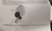 em 2 (20 Points Total): The figure below shows a motor (characterized by an inertia J, and a rotational ping Orl) driving a flywheel with a bearing (characterized by a second inertia J; and a rotational damping bra through a set of gears with radii R. and R. The input is a motor torque M.0), and the coordinates are defined as shown in the figure. Assume the shafts are rigid. 02,6 flywheel bile J byl motor M.,,, Complete the following....
Ih, head inertia flexible shaft k, b I, motor inertia rn b, motor friction 6. Show...
 Ih, head inertia flexible shaft k, b I, motor inertia rn b, motor friction 6. Show that the equations of motion for the disk-drive system are given by: where motor inertia θm = motor position Pn-head position b-shaft damping bm-motor bearing and brush friction Ihead inertia k-shaft stiffness t,n(t) = motor torque input Express the equations of motion in state-variable form using [bmuOh,o,n, θ ] as the state vector. What is the order of this system? Could the dynamics of...
A transfer shaft with two spur gears shown below: Input Gear 1 Output Gear Torque Bearing...
 A transfer shaft with two spur gears shown below: Input Gear 1 Output Gear Torque Bearing 1 Gear 1 Gear 2 Bearing 2 B OTO 4" 4" 4" 4 . . Weight Ibf Teeth number Pressure angle Po (diametric pitch) teeth/in Gear A 50 20° 6 Gear C 2 25 20° 6 Deep groove ball bearings at B and D. Pitch diameter of the gear is equal to the teeth number divided by diametric pitch. Shaft speed = 3000 rpm....
You are the designer and you have been asked to design a speed reducer (gearbox) that will take p...
 power = 3 kW
if need any more information please ask !!!
You are the designer and you have been asked to design a speed reducer (gearbox) that will take power from the shaft of an electric motor rotating at 1500 rpm and deliver it to a machine that is to operate at approximately at 200 rpm Assume that you have decided to use spur gears to transmit the power [A power equal to the last one digits of your...
power = 3 kW
if need any more information please ask !!!
You are the designer and you have been asked to design a speed reducer (gearbox) that will take power from the shaft of an electric motor rotating at 1500 rpm and deliver it to a machine that is to operate at approximately at 200 rpm Assume that you have decided to use spur gears to transmit the power [A power equal to the last one digits of your...
3.2 Pre-Lab Assignment When deriving the governing equations for an electromechanical system, it is often beneficial...
 3.2 Pre-Lab Assignment When deriving the governing equations for an electromechanical system, it is often beneficial to examine the electrical and mechanical components independently. Looking at only the electrical components of the QUBE-Servo DC motor (as shown in Figure 3.2): R v00 C e, (00 Figure 3.2: Electrical curcuit of the QUBE-Servo DC motor Q1. Write the differential equation in the form of Kirchoff's voltage law) in the Laplace domain for the electrical circuit (do not use parameter values given...
 i want to get part c,d
The figure below is a gear-train mechanical system driven by a prescribed motion in the form of an angular displacement y(t). The motion is caused by an applied torque T(t) generated by a motor. The mass moment of inertias of the motor and the driving gear are J and J, respectively, whereas the mass moment of inertias of the load and the driven gear are J, and J2, respectively. The radii and angular displacements...
i want to get part c,d
The figure below is a gear-train mechanical system driven by a prescribed motion in the form of an angular displacement y(t). The motion is caused by an applied torque T(t) generated by a motor. The mass moment of inertias of the motor and the driving gear are J and J, respectively, whereas the mass moment of inertias of the load and the driven gear are J, and J2, respectively. The radii and angular displacements...
 Homework 6: The figure below shows a gear train where gear 1, on shaft a (input shaft), drives gear 2 with 32 teeth (denoted 32T) on shaft b, gear 3 (20T) also is on shaft b and drives gear 4 (507) on shaft c (output shaft). The pitch diameter of gears 1 and 2 are d = 24 mm and d = 48 mm. The center distance between gears 3 and 4 (distance between shafts b and c is 70mm....
 Q 1- 08 Pts) Figure below is a diagram of a DC motor connected in parnllel to a current source i,. The torque and back-EMF constants of the motor are Ko K respectively, the motor resistance is R, also modeled as connected in parallel, the motor inertia is 1- (not shown), and the motor inductance is negligible. The motor load is an inertia J with compliance (stiffness) K and viscous friction coefficient b, and it is attached a gear pair...
 01- (08 Pts) Figure below is a diagram of a DC motor connected in parallel to a current source is the torque and back-EMF constants of the motor are K. K respectively, the motor resistance is R, also modeled as connected in parallel, the motor inertia is I. (not shown), and the motor inductance is negligible. The motor load is an inertia compliance (stiffness) K and viscous friction coefficient b, and it is attached to the motor via a gear...
 em 2 (20 Points Total): The figure below shows a motor (characterized by an inertia J, and a rotational ping Orl) driving a flywheel with a bearing (characterized by a second inertia J; and a rotational damping bra through a set of gears with radii R. and R. The input is a motor torque M.0), and the coordinates are defined as shown in the figure. Assume the shafts are rigid. 02,6 flywheel bile J byl motor M.,,, Complete the following....
 Ih, head inertia flexible shaft k, b I, motor inertia rn b, motor friction 6. Show that the equations of motion for the disk-drive system are given by: where motor inertia θm = motor position Pn-head position b-shaft damping bm-motor bearing and brush friction Ihead inertia k-shaft stiffness t,n(t) = motor torque input Express the equations of motion in state-variable form using [bmuOh,o,n, θ ] as the state vector. What is the order of this system? Could the dynamics of...
 A transfer shaft with two spur gears shown below: Input Gear 1 Output Gear Torque Bearing 1 Gear 1 Gear 2 Bearing 2 B OTO 4" 4" 4" 4 . . Weight Ibf Teeth number Pressure angle Po (diametric pitch) teeth/in Gear A 50 20° 6 Gear C 2 25 20° 6 Deep groove ball bearings at B and D. Pitch diameter of the gear is equal to the teeth number divided by diametric pitch. Shaft speed = 3000 rpm....
 power = 3 kW
if need any more information please ask !!!
You are the designer and you have been asked to design a speed reducer (gearbox) that will take power from the shaft of an electric motor rotating at 1500 rpm and deliver it to a machine that is to operate at approximately at 200 rpm Assume that you have decided to use spur gears to transmit the power [A power equal to the last one digits of your...
power = 3 kW
if need any more information please ask !!!
You are the designer and you have been asked to design a speed reducer (gearbox) that will take power from the shaft of an electric motor rotating at 1500 rpm and deliver it to a machine that is to operate at approximately at 200 rpm Assume that you have decided to use spur gears to transmit the power [A power equal to the last one digits of your...
 3.2 Pre-Lab Assignment When deriving the governing equations for an electromechanical system, it is often beneficial to examine the electrical and mechanical components independently. Looking at only the electrical components of the QUBE-Servo DC motor (as shown in Figure 3.2): R v00 C e, (00 Figure 3.2: Electrical curcuit of the QUBE-Servo DC motor Q1. Write the differential equation in the form of Kirchoff's voltage law) in the Laplace domain for the electrical circuit (do not use parameter values given...
Most questions answered within 3 hours.
-
Where is the error in this code sequence?
String s1 = "Hello";
String s2 = "ello";...
asked 11 months ago -
Financial data for Joel de Paris, Inc., for last year
follow:
Joel de Paris, Inc.
Balance...
asked 11 months ago -
Consider this reaction:
Al2(SO4)3 (aq)+ BaCl3
(aq) Al2Cl6 (aq)- +
3BaSO4(s) . What is the...
asked 11 months ago -
Suppose that Savneet is considering increasing her
recent random sample from 20 car rentals to 40...
asked 11 months ago -
Trucks arrive at an unloading terminal at an average rate of 120
per hour.
Trucks arrive...
asked 11 months ago -
Why are methanol and ethanol completely soluble in water while
octanol is not very little soluble....
asked 11 months ago -
A facilities manager at a university reads in a research report
that the mean amount of...
asked 11 months ago -
When the CuSO4 is rehydrated by adding water to the anhydrous
compound, is this an endothermic...
asked 11 months ago -
A ray of sunlight is passing from diamond into crown glass; the
angle of incidence is...
asked 11 months ago -
A block of mass 0.249 kg is placed on top of a light, vertical
spring of...
asked 11 months ago -
how do the kidneys compensate in the presences of acidosis
a) trigger hyperventilate
b) reserve acid...
asked 11 months ago -
Question 501 pts
The rental rate of capital to the firm increases. Which of the
following...
asked 11 months ago