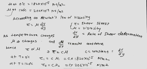
![2. Determine the percentage change in the force caused by shear stress if the lubricant warms up from 0 to 120°C. [5 marks] u](http://img.homeworklib.com/questions/612a9c70-5b6d-11ec-a11d-11066b9d24d0.png?x-oss-process=image/resize,w_560)
Homework Answers

Add Answer to:
2. Determine the percentage change in the force caused by shear stress if the lubricant warms...
Question 4: Shear stress in a beam (40 marks) Consider the beam section illustrated in the figure to the right. The beam has a shearing force of V = 5 kN acting vertically through the shear center as...
 Question 4: Shear stress in a beam (40 marks)
Consider the beam section illustrated in the figure to the
right. The beam has a shearing force of V = 5 kN acting vertically
through the shear center as illustrated. (a) Determine the shear
stress at the three points in the beam section labelled (i), (ii),
and (iii). [20 marks] (b) Produce a plot showing the direction and
distribution of shear stress across the beam section, noting the
shape of the...
Question 4: Shear stress in a beam (40 marks)
Consider the beam section illustrated in the figure to the
right. The beam has a shearing force of V = 5 kN acting vertically
through the shear center as illustrated. (a) Determine the shear
stress at the three points in the beam section labelled (i), (ii),
and (iii). [20 marks] (b) Produce a plot showing the direction and
distribution of shear stress across the beam section, noting the
shape of the...
(a) Briefly explain Mohr-Coulomb theory and show how we can determine the shear strength parameters of...
(a) Briefly explain Mohr-Coulomb theory and show how we can determine the shear strength parameters of soil by plotting the shear stress versus normal stress. [3 marks] The following results were obtained from a consolidated undrained Triaxial (CU) test with pore water pressure measurement on three samples of a fully saturated clay. Determine the total (undrained) stress and effective (drained) stress parameters. [12 marks] Sample Cell pressure (kN/m2) Deviator stress at failure (kN/m2) Pore pressure at failure (kN/m2) A 300...
Problem 25 Determine the maximum transverse shear stress on the section if the internal shear force...
 Problem 25 Determine the maximum transverse shear stress on the section if the internal shear force is V = 5 kips. 32 in V - 5 kips ]12 in & in 1 = 426.67 in 2 in a) 375 psi b) 23 psi c) 750 psi d) 47 psi e) None of the above
10.13. The shear stress, Tw, on a flat surface that is caused by a fluid of density p and vis- cosity u flowing over the surface at a velocity V is given by where Re,- V Re where r is the distance fr...
 10.13. The shear stress, Tw, on a flat surface that is caused by a fluid of density p and vis- cosity u flowing over the surface at a velocity V is given by where Re,- V Re where r is the distance from the upstream end of the flat surface. (a) Use the given shear stress distribution, w(x), to determine the drag force on a flat plate of width W and length L in terms of W, L, V, p,...
2. Draw Shear Force and Bending Moment Diagram (use your preferred method). Determine Maximum Ten...
 2. Draw Shear Force and Bending Moment Diagram (use your preferred method). Determine Maximum Tensile and Compressive Stresses due to bending, state where on the beam these occur. For the mid-point between A and B, determine shear stress at neutral axis; 2" from the top of the flange; at the junction between web and flange and on the top of the flange for the cross-section. Plot of the bending stress and shear stress distribution diagram across the cross section of...
Assume that if the shear stress in steel exceeds about 4.0o x 108 N/m2, the steel...
 Assume that if the shear stress in steel exceeds about 4.0o x 108 N/m2, the steel ruptures. (a) Determine the shearing force necessary to shear a steel bolt 1.45 cm in diameter. (b) Determine the shearing force necessary to punch a 1.05-cm-diameter hole in a steel plate 0.800 cm thick. Step 1 (a) we know that force F is equal to the surface area A times stress σ so we have 4 108 N/m 2 Your response differs from the...
Determine the maximum shear stress in a W12 X 40 steel I-beam using the simplified Shear...
 Determine the maximum shear stress in a W12 X 40 steel I-beam using the simplified Shear Stress equation for steel shapes. It has been determined from Statics that the internal shear force is 30 kip. A18 APPENDIX C Properties of Rolled-Steel Shapes (U.S. Customary Units) Continued from page A17 W Shapes (Wide Flange Shapes Flange Web Thick Thick Width nessness by in. in. toin. Axis X-X Axis Y-Y Area Ain? Depth d. in. in Sy, in Fin. Designationt W12 X...
Learning Goal: To calculate torsional deformation and shear stress due to an applied force in a...
 Learning Goal: To calculate torsional deformation and shear stress due to an applied force in a door handle design. A locked door handle is composed of a solid circular shaft AB with a diameter fb = 105 mm and a flat plate BC with a force P = 76 N applied at point C as shown. Let c = 543 mm, d = 125 mm, and e = 145 mm. (Treat the handle as if it were a cantilever beam.)...
Given a shearing force V of 150kN: -Determine the maximum, minimum and average shearing stresses in...
 Given a shearing force V of 150kN:
-Determine the maximum, minimum and average shearing stresses in
the vertical web of the I-type cross section. Compare the
magnitudes of these shear stresses. What is your conclusion? (Note:
the average shear stress in the web is the shear force/area of the
web)
-Determine the shear stress in the flange at a distance of 95mm
from the tip (point X).
Question 1 (30 marks) Given a shearing force V of 150 kN: Determine...
Given a shearing force V of 150kN:
-Determine the maximum, minimum and average shearing stresses in
the vertical web of the I-type cross section. Compare the
magnitudes of these shear stresses. What is your conclusion? (Note:
the average shear stress in the web is the shear force/area of the
web)
-Determine the shear stress in the flange at a distance of 95mm
from the tip (point X).
Question 1 (30 marks) Given a shearing force V of 150 kN: Determine...
Learning Goal: To calculate torsional deformation and shear stress due to an applied force in a...
 Learning Goal: To calculate torsional deformation and shear stress due to an applied force in a door handle design. A locked door handle is composed of a solid circular shaft AB with a diameter of b = 101 mm and a flat plate BC with a force P = 77 N applied at point C as shown. Let c = 473 mm, d = 126 mm, and e = 148 mm (Treat the handle as if it were a cantilever...
 Question 4: Shear stress in a beam (40 marks)
Consider the beam section illustrated in the figure to the
right. The beam has a shearing force of V = 5 kN acting vertically
through the shear center as illustrated. (a) Determine the shear
stress at the three points in the beam section labelled (i), (ii),
and (iii). [20 marks] (b) Produce a plot showing the direction and
distribution of shear stress across the beam section, noting the
shape of the...
Question 4: Shear stress in a beam (40 marks)
Consider the beam section illustrated in the figure to the
right. The beam has a shearing force of V = 5 kN acting vertically
through the shear center as illustrated. (a) Determine the shear
stress at the three points in the beam section labelled (i), (ii),
and (iii). [20 marks] (b) Produce a plot showing the direction and
distribution of shear stress across the beam section, noting the
shape of the...
 Problem 25 Determine the maximum transverse shear stress on the section if the internal shear force is V = 5 kips. 32 in V - 5 kips ]12 in & in 1 = 426.67 in 2 in a) 375 psi b) 23 psi c) 750 psi d) 47 psi e) None of the above
 10.13. The shear stress, Tw, on a flat surface that is caused by a fluid of density p and vis- cosity u flowing over the surface at a velocity V is given by where Re,- V Re where r is the distance from the upstream end of the flat surface. (a) Use the given shear stress distribution, w(x), to determine the drag force on a flat plate of width W and length L in terms of W, L, V, p,...
 2. Draw Shear Force and Bending Moment Diagram (use your preferred method). Determine Maximum Tensile and Compressive Stresses due to bending, state where on the beam these occur. For the mid-point between A and B, determine shear stress at neutral axis; 2" from the top of the flange; at the junction between web and flange and on the top of the flange for the cross-section. Plot of the bending stress and shear stress distribution diagram across the cross section of...
 Assume that if the shear stress in steel exceeds about 4.0o x 108 N/m2, the steel ruptures. (a) Determine the shearing force necessary to shear a steel bolt 1.45 cm in diameter. (b) Determine the shearing force necessary to punch a 1.05-cm-diameter hole in a steel plate 0.800 cm thick. Step 1 (a) we know that force F is equal to the surface area A times stress σ so we have 4 108 N/m 2 Your response differs from the...
 Determine the maximum shear stress in a W12 X 40 steel I-beam using the simplified Shear Stress equation for steel shapes. It has been determined from Statics that the internal shear force is 30 kip. A18 APPENDIX C Properties of Rolled-Steel Shapes (U.S. Customary Units) Continued from page A17 W Shapes (Wide Flange Shapes Flange Web Thick Thick Width nessness by in. in. toin. Axis X-X Axis Y-Y Area Ain? Depth d. in. in Sy, in Fin. Designationt W12 X...
 Learning Goal: To calculate torsional deformation and shear stress due to an applied force in a door handle design. A locked door handle is composed of a solid circular shaft AB with a diameter fb = 105 mm and a flat plate BC with a force P = 76 N applied at point C as shown. Let c = 543 mm, d = 125 mm, and e = 145 mm. (Treat the handle as if it were a cantilever beam.)...
 Given a shearing force V of 150kN:
-Determine the maximum, minimum and average shearing stresses in
the vertical web of the I-type cross section. Compare the
magnitudes of these shear stresses. What is your conclusion? (Note:
the average shear stress in the web is the shear force/area of the
web)
-Determine the shear stress in the flange at a distance of 95mm
from the tip (point X).
Question 1 (30 marks) Given a shearing force V of 150 kN: Determine...
Given a shearing force V of 150kN:
-Determine the maximum, minimum and average shearing stresses in
the vertical web of the I-type cross section. Compare the
magnitudes of these shear stresses. What is your conclusion? (Note:
the average shear stress in the web is the shear force/area of the
web)
-Determine the shear stress in the flange at a distance of 95mm
from the tip (point X).
Question 1 (30 marks) Given a shearing force V of 150 kN: Determine...
 Learning Goal: To calculate torsional deformation and shear stress due to an applied force in a door handle design. A locked door handle is composed of a solid circular shaft AB with a diameter of b = 101 mm and a flat plate BC with a force P = 77 N applied at point C as shown. Let c = 473 mm, d = 126 mm, and e = 148 mm (Treat the handle as if it were a cantilever...
Most questions answered within 3 hours.
-
Where is the error in this code sequence?
String s1 = "Hello";
String s2 = "ello";...
asked 10 months ago -
Financial data for Joel de Paris, Inc., for last year
follow:
Joel de Paris, Inc.
Balance...
asked 10 months ago -
Consider this reaction:
Al2(SO4)3 (aq)+ BaCl3
(aq) Al2Cl6 (aq)- +
3BaSO4(s) . What is the...
asked 10 months ago -
Suppose that Savneet is considering increasing her
recent random sample from 20 car rentals to 40...
asked 10 months ago -
Trucks arrive at an unloading terminal at an average rate of 120
per hour.
Trucks arrive...
asked 10 months ago -
Why are methanol and ethanol completely soluble in water while
octanol is not very little soluble....
asked 10 months ago -
A facilities manager at a university reads in a research report
that the mean amount of...
asked 10 months ago -
When the CuSO4 is rehydrated by adding water to the anhydrous
compound, is this an endothermic...
asked 10 months ago -
A ray of sunlight is passing from diamond into crown glass; the
angle of incidence is...
asked 10 months ago -
A block of mass 0.249 kg is placed on top of a light, vertical
spring of...
asked 10 months ago -
how do the kidneys compensate in the presences of acidosis
a) trigger hyperventilate
b) reserve acid...
asked 10 months ago -
Question 501 pts
The rental rate of capital to the firm increases. Which of the
following...
asked 10 months ago